 The
payload is lifted by an airplane (airplane approach: dashed line) to
attach to the leading end of the horizontal rope.
The
payload is lifted by an airplane (airplane approach: dashed line) to
attach to the leading end of the horizontal rope. (Fine dotted line: The satellite orbit)
Leaving Earth
pulled by an orbiting locomotive
Introduction
Getting a payload in orbit is very expensive, as it takes much energy to achieve the required speed and altitude. But the costs are unnecessarily high because:
Rockets must deliver strong forces for a short time, and afterwards they are dead weight.
The energy must be supplied in refined form – as expensive high-grade fuel.
Most of the fuel is wasted on lifting and accelerating fuel.
The huge amounts of fuel necessitate large, multistage, single-use rockets.
The scheme to be presented here enables:
small rockets to be used, as they can be doing useful work during long periods
most of the fuel to be replaced by solar energy
one launch mechanism to be reused for many launches.
Power waste is replaced by intelligence.
The principle is: A satellite with much kinetic energy (in a highly eccentric orbit) gives some of its energy to a near-ground payload module when passing near it. The payload module is then pulled into orbit, and the satellite continues in a low energy (nearly circular) orbit. The satellite's solar cell driven electrostatic thrusters will then within a few days accelerate the satellite to the previous high energy orbit. The minimum height above the earth surface (at perigee) should be approximately the same, but the maximum height (at apogee) will vary strongly, reflecting the energy reserve of the launch mechanism. If a satellite in low circular orbit gets its kinetic energy doubled, it reaches the escape velocity and escapes from the earth's gravity. In practice, the maximum distance should be limited to avoid disturbances from the moon, and perhaps be adjusted to give frequent enough passes near launch sites used.
If we say that an object at rest far away from the Earth has zero energy, and that satellites moving closer and closer to the Earth have stronger and stronger negative energy, we may have a counterintuitive energy scale, but it is now easy to compute energies for the different orbits: The orbital energy is given by the length of the major axis (the “maximum diameter”) of the orbital ellipse. Viewing energies in this manner makes the shape of the gravitational potential well quite apparent: This well flattens out at high altitudes, so little energy capacity is lost if we avoid these altitudes.
We may conclude that our space locomotive mechanism could weight a few tons and lift into orbit a payload module having 80-90 % of that weight.
The launch mechanism
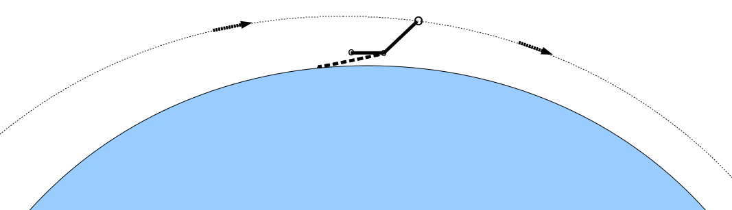
A satellite could not go much below 200 km before the drag becomes problematic. The payload could be lifted by quite conventional aircraft to at least 15 km, perhaps more than the 50 km the stratosphere stretches to. The gap is bridged by a carbon rope having two parts. The first part goes down from the satellite to the stratosphere, and the second part flies horizontally where the payload acceleration takes place. The payload module grabs the horizontal rope lightly – enough to be accelerated to orbital speed with a g-force bearable to people who are not pilots/astronauts.
The
payload is lifted by an airplane (airplane approach: dashed line) to
attach to the leading end of the horizontal rope.
(Fine dotted
line: The satellite orbit)
If the payload can be accelerated with 5 g to a speed of 8 km/s, the horizontal acceleration stretch must be 640 km. This would entail too much rope to align horizontally in an altitude which is a small fraction of the rope length. But most of this acceleration stretch could be created during the acceleration – after the payload module has grabbed the horizontal rope. Increasing the speed by 8 km/s using a 5 g acceleration takes about 8000/(5x9.8)=163 seconds. If both end parts of both ropes were reeled up (like commonly used key chains), and each reel could release one kilometer rope per second, the four reels could give 652 km. (There could be additional, double reels on the middle of the down-going rope, and on the up-going rope from the payload module – and even several on each of these stretches.)
The horizontal rope might come flying with something like 50-100 km rope exposed for grabbing. The last reel would give extra rope for grabbing, and all the reels ahead would buy extra time for the acceleration process – equivalent to providing really accelerating rope. Brakes at the reels will help spreading the braking power dissipation.
Releasing rope at one km/s may be difficult using conventional unreeling. If it is, the rope can be pulled off from the end of the reel. If one of the four+ unreelings should get jammed, it shouldn't be too serious if the acceleration then increased to 6-7 g.
Grabbing a rope that comes flying at perhaps 10 km/s is serious business, even though the friction will quite soon be shared by several rope dispensers. The heating of the rope will be well distributed along very much rope, and carbon can withstand temperatures up to about 3600 °C. The braking clamps will need special arrangements for spreading and radiating heat.
Friction losses can be greatly reduced if pulsed clamping is used – by alternating between full and zero clamping, combined with springing action for smoothing out the movement. This would be a mechanical equivalent to the pulse modulation electronics employed for increasing the efficiency of high-power circuits. It should also be possible to design a non-contact force engagement device. If the rope could have conductor coils, or at least conducting mass permitting eddy currents, it could work as a linear (motor/)generator, perhaps using the Inductrack principle.
Movement options
It would be advantageous if the launch mechanism were rotating, so that its lower part were moving backwards in relation to the satellite when passing the launch (clamp) site. Atmospheric drag will cause such rotation.
Advantages of rotation before attachment of payload:
It keeps the upper rope straight in whatever direction is desired at clamp time.
The lower part of the mechanism can spend less time in the atmosphere.
The horizontal rope will come with a lower speed – perhaps 1-2 km/s lower.
Disadvantages:
It will be difficult to get the lower rope up in horizontal position.
Even if the back end of the lower rope were lifted to correct height, the middle part would hang down, as this rope would no longer be weightless.
When a payload module attaches itself to the lower part of a non-rotating launch mechanism, rotation will then start anyway, but not so fast. Rapid rotation after attachment has the advantage that the payload module can be thrown away, as by a sling, in various directions simply by letting go of the rope at the right moment – after 0 to ½ rotation around the satellite. After ½ rotation, this sling rotation speed is added to the speed of the satellite. If the sling rotation speed is 3 km/s, a satellite in low Earth orbit can throw a payload to the Moon. If half a rotation can be done near perigee, the payload will have a good orbit, getting a perigee well above the atmosphere. If there is no rotation, the gravity gradient should keep the upper rope straight, with the lower bodies somewhat ahead of the upper. At grab time (at perigee) the air resistance will pull the lower bodies backwards.
Recharging the mechanism
When a large payload module has been launched, the satellite will be in a low and nearly circular orbit, and its energy has to be increased. This implies rockets pulling up the apogee (without lifting perigee). It may be ok to give the mechanism several days for this, so ion thrusters or magnetoplasmadynamic thrusters may be used for this purpose. They are weak, but very efficient. They don't really use fuel, just some propellant to throw away. These thrusters are driven by electricity, so by using solar cells, fuel needn't be supplied. But even if conventional rockets are used, they would be quite efficient, as fuel can be delivered to them by conventional aircraft. When a special service/fueling vehicle has attached itself, the ropes are fully reeled in, and the entire mechanism can receive fuel and maintenance.
Flexibility
A large range of operating modes is available through adjusting parameters like orbit and rope lengths. One important mode is cargo delivery, in which case high acceleration like 20 g can be used. The horizontal rope can then be short, and the mechanism can rotate rapidly – for sending cargo by the slingshot procedure as mentioned above.
The recharging process can continue to give an orbit beyond the highest Earth orbits, so that the mechanism can fly to the Moon by itself and go into operational orbit there. The slingshot procedure can there occasionally be used reversed – for receiving payloads thrown from Earth.
During recharging, the orbit may by tilted gradually, even up to polar orbit, so airports anywhere on Earth may be the point of departure, using a short airplane trip at takeoff.
The structure of the mechanism
The main body, the upper part, is what we have been calling the satellite – although the entire launch mechanism constitutes one satellite.
It needs:
mass – for imparting its momentum to the payload
thrusters/rockets for regaining lost momentum
solar cells for powering the thrusters
a reel for the down-going rope
A large amount of fuel (or another liquid later supplied in the same manner) may be employed simply for increasing the mass.
The central body needs reels for both the upwards-going and the backwards-going rope. It also needs air control surfaces (stabilizers/elevators), and some small rockets for position control.
The rear body – at the trailing end of the horizontal rope – needs one rope reel. It also needs position control devices like those the central body has. It should also have an airbrake for straightening the rope in the upper atmosphere. The airbrake and/or braking rockets will be needed for preventing the last part of the horizontal rope from coming flying forwards upon the payload module when this decelerates the entire mechanism.
The rockets on these two bodies may also be used for orbit rising.
The ropes should ideally be made of carbon nanotubes, but conventional carbon ropes should be ok. The extra weight will help giving the mechanism high momentum, but for the rope after the payload, heavy rope will cause energy loss due to the stronger braking needed at the end. If the rope could open up like a tube or rope ladder, it would not be so easily cut by a small meteorite or orbiting object.
The payload module should have a central grabber with two payload containers, one on each side. The payload will then be less endangered by that energetic rope, and the rope can pull near the mass center of the payload module. One of the two containers may routinely be a fuel tank.
A rope grabber (brake) may be permanently on the horizontal rope (initially at the front end), and have a hook (a skyhook) on its bottom. The payload module can then sit and wait on the ground, attached to the lower end of a rope which has a loop on the upper end. The loop us lifted up to the path of the skyhook by e.g. a (moderately dirigible) balloon. Also this rope could have reels at the ends, and then also these reels would contribute reducing the forces and power dissipation at the grabbing point. But the many reels wouldn't work well together if their inertias added up simultaneously. Slippage at the grabbing point will remedy this by yielding more while reels start spinning.
Safety
To ensure against dangerous acceleration, the payload module's connection with the grabber should break if the acceleration exceeds e.g. 10 g.
That long and strong rope would be dangerous if it were dragged along the ground, so it should then be released automatically, and it might be chemically treated to ignite if flying rapidly though a high oxygen concentration.
At Lagrange points
It may be advantageous to have large but simple structures – a few rope-connected bodies – placed at fixed positions in relation to the Earth. The Lagrange points are well suited for this, particularly L1 and L2 for the Earth-Moon system, or for the Sun-Earth system. These are unstable for movements along the axis going through the two large masses, but stable for for movements orthogonally in the orbit plane. Along the dimension of unstability, a long structure spanning across the Lagrange point will be stretched out, because the saddle point gradients (particularly at L1) cause separation along this dimension. (See the first figure in the Wikipedia article Lagrange points.)
But it will generally be more interesting to have such large structures oriented with a large surface facing the Sun. If a large surface is required, there should be long rods (or inflatable tubes) orthogonally to the rope – optionally holding apart two parallel ropes. A membrane – e.g. a flexible solar panel – stretched across this structure will look like a hammock. If such a structure is placed in L1 between the Sun and the Earth, it can keep facing the Sun throughout the year, unlike similar structures in Earth orbit or in an Earth-Moon Lagrange point. If such a sunshade covers a few percent of the Earth, it should significantly reduce global warning.
Ropes forming a sun-oriented surface will not be stretched out by the potential gradients at the Lagrange points. The ropes may be hollow – flexible tubes which are straightened out by a gas released inside them. The gas will leak out, so the tubes should be chemically treated to become rigid after having been exposed to sunlight for a while.
To Mars
Just like the whole mechanism could go to the Moon, it could go to Mars. An important advantage of flying to Mars with such a rotating mechanism – with a few space ships separated by long ropes – is: The crew can get a decent artificial gravity without spinning too fast.
The rotation should be in a plane orthogonally to the flight direction. The outer bodies should have thrusters which can be directed for forward movement and for (propeller-resembling) rotation. The solar driven, low-power thrusters recommended above are well suited for traveling to Mars. They will be used for acceleration during the first half of the journey, and for deceleration during the second half.
A body near the center (near the rotational axis) may also be a suitable carrier for propulsion thrusters. But this stabilized position may rather be reserved for the antennas – for communication with Earth. The extreme width of this multi-hulled spaceship enables a good separation between radio antennas and thrusters, whose ionized gas jet, when directed backward towards Earth, would severely disturb radio communication. (If these jets still disturb communication, backwards-directed jets may have to be replaced by combinations of somewhat outwards-directed jets.)
The size and rotation of this mechanism enables conventional rigid solar panels to be replaced by a large, flexible “solar sail” panel, which could be large enough to connect to (and thus power) two or three bodies. (A really large sail like this could also give propulsion from the solar light pressure, but only for an outwards journey.)
When the mechanism reaches Mars, it could put down and pick up a landing module by operating just like in Earth orbit. When passing a Mars moon – Phobos or Deimos – it could adjust the rotation so that one end of the mechanism would be nearly stationary relative to the moon. It would then be possible to deposit equipment on this moon, and pick it up later – for instrumentation, mining, etc.. And a non-gravitational swing-by is possible if a moon (or asteroid) is permitted to hit and snag a rope. The relative speed can't be high, but a significant momentum change can be obtained if the rope hangs on through e.g. half the orbit.
Mars is well suited for picking up and depositing cargo/passenger modules by means of ropes swinging down to the surface. This is due to the thin atmosphere there: Its pressure at the mean surface is .6 % of the Earth's. And on the highest point (Olympus Mons) it is only 5 % of this again. The lower bodies of the mechanism will just need large wings.
Dealing with asteroids
Such a rope mechanism would also be useful for dealing with asteroids – mainly for collecting minerals or ice. This could mean:
Examining them (with laser beam heating and spectroscopy?)
Catching small asteroids (and optionally dispatching them by sling, giving them a controlled landing on Earth by reversed use of a rotating rope launcher)
Landing on large asteroids. With favorable/controlled asteroid rotation conditions (especially on a sun-lit pole) heating by focused sunlight might melt the surface for processing.
This could be done in the main asteroid belt beyond the Mars orbit – mainly for getting what is needed on Mars. But many asteroids are close to the Earth's orbit, and they should be checked out first – for minerals needed on the Moon and Earth.
When mining during the space flight, it should be easier to find matter suitable for ion thruster acceleration than to find fuels.
Rope-based structures can control and manipulate objects along a wide path. When the movements of these objects are accurately mapped in advance, intelligently adjusted rotation can be used instead of frequent rocket-propelled speed changes, and the rope-based structures, having a catching net on one end, will be well suited for handling quite rapidly moving objects.
Such asteroid handling activities will also make it possible to protect Earth against asteroids coming on a collision course. One elegant method for course modification could be to use a long rope (either elastic, or extendable, braked by a friction latch) with coarse nets at both ends. One net catches the dangerous asteroid, and the other net catches an asteroid having a suitable correcting course.
Applying high voltages to parts of the rope enables acceleration of the whole assembly by means of the Biefeld-Brown effect. (Experiments by Townsend Brown in France showed that this effect also works in a vacuum.)
Comparison with the space elevator
The proposed space elevator, with a more than 36000 km long rope going straight up from the Earth's equator, has for some strange reason become positioned as a serious solution for economical space launching. That long rope will experience high gravity forces and must have varying thickness. Our orbiting alternative, however, will need less than 2 % of the rope length, and with less worrying about thickness variation and strength.
The elevator will have a low launch capacity because the cable will be occupied by a slowly moving vehicle (which will have energy supply problems). The orbiting device can have high capacity if it uses conventional rockets.
The elevator rope will stand in a stream of several thousand satellites and fragments passing by at about 8-9 km/s, while the smaller orbiting alternative will go with this stream, have exchangeable parts, and can reel in its ropes in periods of inactivity.
Such a grandiose elevator will certainly be tempting for terrorists, and very difficult to defend. It could be attacked with explosives, by shooting, or with an airplane with knife blades on a wing edge. An orbiting device, however, will be far better protected.
Olav Næss, November 2009
Updates:
April 7th 2010: New paragraph: At Lagrange points
April 14th 2010: Small vs. large rockets mentioned in Introduction