
Here is a cross-section of the next generation beam, showing how the wheels run in it.
The next generation beamway has no beam, and the next generation trains have no wheels.
by Olav Naess
Here
is a cross-section of the next generation beam, showing how the
wheels run in it.
The next
generation beamway has no beam, and the next generation trains have
no wheels.
This article is about the spear train, as mentioned in “Are Strong Beams Needed?”. The other beamway articles on this site are about the 2C beam: a steel beam consisting of two C-shaped half-beams. To prevent unnecessary confusion, the alternative beamway type – the beamless type – is described here, in a separate article.
It was stated about the spear train that it could manage without a beam if it could carry along its own beam, which flew like a spear through a sequence of rings forming a straight line, each ring on top of its pole. The length of the spear was supposed to be more than twice the distance between the poles.
The first generalization is: The train can turn to the side (following a curved alignment of rings) if the spear can bend to the sides like a spine, but retain its stiffness vertically (and of cause not roll to any side).
The second generalization is: The train can also turn upwards or downwards by replacing its stiffness with a well controlled spine bending which doesn't yield to gravity, but strongly enforces an adaptation to the vertical contour of the track.
For safety reasons, only weak curvatures are permitted. This follows from the following principle for adaptive train shape control:
The spine is almost a spear, as it can only bend a little. This means the radius of track curvature must be quite large, so the design is for high-speed, long distance trains. It bends horizontally and vertically under computer control, guided by the detected direction to the next ring, and/or the direction data it has for this ring position in its database. The train may of cause not fly out in the blue if computer control or power is lost, so some simple mechanical fallback mechanisms must ensure correct tracking, although in a more brutal manner.
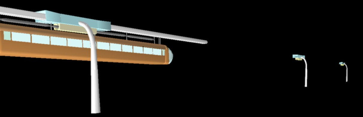
A
conventional train is here attached under a flying spear.
The
total spine strength of the spear alone is likely to be too small.
This picture shows how the rectangular “ring” on top of each pole has a certain length, so that it can act as a guiding tube and apply its forces to the rectangular spear in a smooth and efficient manner. The first part of the tube is funnel-shaped in order to correct for moderate misalignment. The first part of the spear should be able to yield readily to this mechanical deflection, so that the spear will be deflected reasonably smoothly. The internal walls of the tube should also be elastically mounted. This mechanical mechanism will hopefully be needed rarely, as the spear should be able to aim and bend accurately enough.
Each pole could have an air blower which sends out an air stream through holes in the floor, the side walls, and perhaps the ceiling of the tube while a spear is passing, so that the spear slides on a cushion of air. (And birds would be scared away.) But a less mechanical method would be more reliable: Maglev (magnetic levitation), and especially the simplified version called Inductrack, whose track magnets are simply unpowered coils in the track. The train can certainly have a set of these coils in the beam it brings along, and a set of electromagnets for repelling these coils will be placed in each tube. Alternatively, there could be a short stretch of unpowered coils in each tube, and powered coils in the spear, but that would require a more intensive (inductive) power transfer to the train, so that would bring us back to the previous arrangement.
First fallback mechanism: Water is squirted out, so that the spear aquaplanes. This could also be done from the first part of the spear.
Second fallback mechanism: The inner walls of the tube are plated with a special polyethylene (UHMWPE), which is quite strong and slippery. The spear should be plated with the same, so that it can slide quite well without any lubrication. Using sliding contact down on the ground, would be quite unthinkable, as it is too sensitive to disturbances from dust and debris. But at beamway altitudes, the conditions are far better.
When the train now is ready to slide, it doesn't mean it will really be doing it, but rather that it now can fly on a thin air cushion or a magnetic field with greater safety.
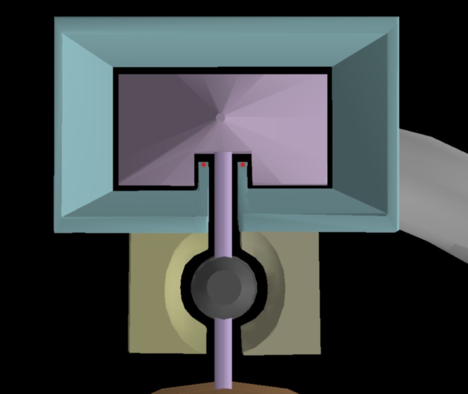
A
spear passing through the guiding tube
The angularity of the
profile will hopefully reduce the leakage of air to the wrong
surface.
The red dots indicate where safety wires to the next
tube may be attached.
Such wires should be made of carbon fibers,
so that they don't bend much down in the middle. They may not be much
touched by spears on straight stretches. In curves, it may be better
to replace them with beams measuring e.g. 3x25 cm.
Under the tube, we see a linear motor (described in the main BeamTech article). These will be omitted if maglev is used, and it can give a horizontal force suitable for propulsion. The row of permanent magnets is in these pictures shown hanging like sausages between the suspension rods. But it may be better to replace the suspension rods with vertical plates which are effectively a downwards extension of the spear, thus improving the strength of the spear. This plate system should have slots for the magnets. It should also be able to expand where it passes through the slit in the bottom of the guiding tube, so that a high friction zone here along the plates is pressed against a corresponding high friction zone inside the slit. This will make a quite efficient emergency brake. The ordinary beamway will be a stronger structure in this respect, as many poles are firmly connected. A spear train will engage two poles during an emergency brake, in addition to getting force from some poles behind if there are safety wires.
Laser beams should be sent from tube to tube – to detect accidental misalignment.
The disadvantages of the beamless beamway are listed here.
Copyleft
![]() Olav Næss 2006
Olav Næss 2006