
The elements making up a small beamway train/tram/bus.
(Shapes are not shown in this diagrammatical representation.)
Beamway Technology Recommendations
by Olav Næss, September 2010
Introduction
The Why and the technical How of beamways is discussed in another article on this website: The Beamway – Technical Details.
The present article describes a (hopefully less confusing) subset of technological choices to be recommended for implementation.
The Train
The conventional train has traditionally consisted of a locomotive pulling some unpowered wagons, but modern passenger trains tend to have the locomotive functions (electric motors) integrated in the passenger wagons. This is like a laptop computer: elegant and convenient when everything works well, but awkward when a problematic part needs to be replaced. A wagon or train full of passengers is ill suited for motor replacement.
The beamway train can and should be designed to combine the advantages of both approaches.
The
elements making up a small beamway train/tram/bus.
(Shapes are not
shown in this diagrammatical representation.)
A beamway train should have one or two wagons. An elevator should be in the end of the first wagon, or constitute a separate "wagon" employed between the two real wagons. The wagons hang under a series of "microlocs" – small locomotives handling both the suspension and propulsion. These have traditionally consisted of motorized bogies running inside a hollow beam, but we will mainly use air cushions for holding up the train, and then it will be more appropriate to speak about sleds instead of bogies.
From each sled goes a suspension connection (controlling the height and providing a soft suspension) down to the wagon. The wagon only needs to have the small motors which displace the suspension sideways.
Microlocs might be programmed or remotely controlled for running alone, but will normally work in teams, and usually for carrying a train as depicted above. Alternatively, a team of something like 3-10 microlocs may be connected to a very thin "wagon" which is hardly more than a beam. When this is connected to an end of a train – perhaps the nearest suspension – we have something like a conventional locomotive. Such a miniloc, used before and/or after a train or wagon, can be useful for giving a train some extra pulling power.
Beamways may run on different kinds of beams: The hollow and flat types will be described below. These will require different kinds of microlocs, but the lower part of the microlocs – the suspension rods and their connection to the wagon top – should be standardized, so that the same wagons may be used with different beam types.
Wheels?
Wheels are inefficient for carrying the weight of a train at high speed. The contact between train and track becomes brutal and energy wasting at high speeds. Inflated rubber wheels give a softer ride, but they are unreliable. Sliding along without mechanical contact can be done at high speeds using magnetic fields (maglev) or air cushions. As air cushion hovering can be used with a plain track – without special equipment like electromagnets or coils mounted all the way along the track – it is preferred in this recommendation. But even if wheels are not used for carrying the weight, they are useful for propulsion. Propulsion power can be delivered efficiently from electric hub motors, and positioning the train can be done reliably in hills and strong winds when wheels are used.
When high traction is needed – for acceleration at low speeds, or for hill-climbing – propulsion may have to deliver a force corresponding to perhaps 20 % of the weight. And during normal operation – even for running at high speeds – the force becomes much lower. This means wheels can be used at high speeds, 200 km/h and more. Weak forces also means less vibrations, so that compact steel-reinforced rubber may be used – for high reliability.
Sled (bogie) designs for such hybrid propulsion will be presented below – for both beam types.
Beam Types
We may consider two beam types: the traditional and the optimal.
The traditional (most used) beam for suspended monorail is the hollow SIPEM beam, in which bogies roll on wheels. Its width is approximately the same as its height. This makes room for bogies running on two tracks, so that traditional track switching can be used. But this beam width means the beam can't be bent sideways for fine-tuning the track curvature (nor twisted for starting and ending graded turns), so that this beam type becomes unsuitable for building high-speed train lines. The 2C-beam to be described below solves this problem. The half-beams making up the 2C-beam can also be transported in greater lengths and be mounted in awkward terrain. As the two half-beam splices can be located far apart, the assembled beam can be without weak parts.
The
2C-beam in cross-section
The optimal beam has the track hanging under a truss plate or I-shaped beam which is designed to withstand the weight of the train. (It is actually the oldest type, having been used since 1901 in Wuppertal.)
The Hollow Beam – with two Rails
We are using a combination of wheels and air cushion for the optimal compromise: We are aiming for quite high speeds, but not so high speeds that propulsion (linear motors) must be provided by the track. This means the train line will be as cheep and simple as when plain old-fashoned wheel bogies are used. Wheels are used for pulling (and regeneratively braking) the train, but only to the extent wheel forces are needed. Air cushions lift as much weight as possible, but are controlled to stop lifting before wheel traction is lost. At low speeds, air cushions are unimportant and may be dispensed with. (In case of e.g. compressor failure, the train could still roll along at well beyond 100 km/h, with only moderately annoying delays and mechanical wears.)
As the speed increases, the forces to be excerted by wheels are decreased, so the load carried by wheels may be reduced by perhaps 80 %. (Emergency braking is not done with wheels, but by clamping the beam.) As the air cushions take care of the side forces, the forces acting on the wheels are greatly reduced, so speeds a little above 200 km/h may be achievable. When movement is controlled with wheels, the speed can be accurately controlled while stopping in a hill or in strong winds.
Simple air-surfing vanes could be used instead of compressor-generated air cushions, but investing in air cushion equipment for the bogies gives some extra advantages:
The air cushion action can be accurately controlled.
Low-pressure air cushion pads can be used under the beam.
Pressures in the upper and lower air cushions can be rapidly reversed for resisting wind swing.
Damaged wheels can be assisted by air cushions – also at low speeds.
Air cushion use can be increased for passing gaps – like in switches and crossings.
Proactive Suspension control can be performed by a pneumatic lifter between the bogie and the suspension rods.

Various
kinds of these wheel types may be used
The flanged type to the left will not be interesting, as air cushions acting on the side walls will ensure proper tracking.
The steel wheel in the middle is simple and reliable. It shouldn't be too noisy when most of the forces against the beam are eliminated by air cushion operation. It has the advantage of being thin, giving low air resistance at high speeds.
The special rubber wheel to the right gives higher friction, so more of the train weight can be air cushion carried before the pulling power of the wheels becomes too low. If the rubber part of this wheel is destroyed, the wheel should be able to function well as a steel wheel – at least if the air cushion assistance is automatically increased. Well armored compact rubber should work well here.
The above picture doesn't show how the hub motor occupies most of the wheel, but this is shown in the next picture. The hub motor will in fact be a very thick stationary axle for the wheel, so there is no need for an axle connecting two wheels running side-by-side. This means the bogie can easily adapt to half-beam separation variations.
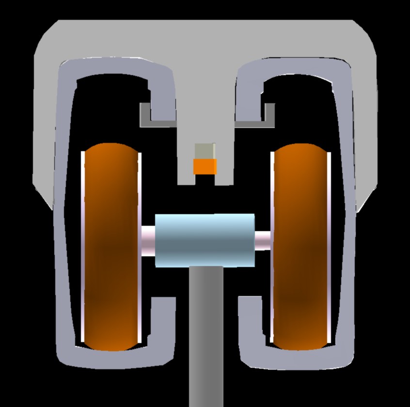
 The
suspension.
The
suspension.
The part inside the train is approximately as shown in
the first picture in the chapter A
Universal Bogie: The suspension can move sideways (passively or
actively) by means of minibogies rolling along roof rails which
follow the curvature of the train roof. But in this design variation
the entire suspension control mechanism (except the motors in the
minibogies) is moved up to a nacelle above the train.
(The gaps
above and below the nacelle should be minimized, so that the train
can still be quite close to the beam, keeping tunnel diameters <4
m.)
This design variation doesn't use a centralized compressor, but has one compressor in each suspension. As the compressed air has to run only a short distance, it will lose little of its heat on the way. This gives energy efficiency as well as little or no problems with freezing at the air cushion pads. (Adiabatic operation)
The bogie, its suspension and compressor hang together as one unit which can easily be detached from the wagon below – because only simple suspension rods (each with a power or signal cable attached) go down to the wagon. (The contents of the nacelle could have been placed in the bogie in the beam, but this would have caused a much stronger air resistance.)
The small distance between the roof rails means that the lifting force from them can continue along one (carbon fiber) strap running around the wagon between windows. It is also easier to protect the train interior against precipitation etc. when there is a narrow slit in the roof.
The minibogies in the top of the wagon should be about half a meter long, and have notches under each end. Horizontal crossbars on the lower end of the two suspension rods are held in these notches. (One notch should be slightly displaceable – to correct for geometric inaccuracies when the minibogies go down the steeper part of the roof rails. ±80 cm displacement should be allowed.)
The picture seems to have one suspension rod going up to a piston in a cylinder marked Lifter. This picture part should be regarded as containing two superimposed suspension rods going up to two lifter cylinders. (A signal cable runs along one of these rods, and a power cable along the other.) Above these cylinders, the upper suspension rods are attached in-line at the central part of the nacelle. These are depicted in two colors for distinguishing those going to the left and right side of the bogie. The short ones go to the air cushion pads working against the bottom of the beam. (These pads should be double, so that the nacelle can be positioned up between them and close to the beam.) The four upper suspension rods are hollow (or supplemented with tubes) for transferring air to or from the air cushion pads. Three such rods/tubes may be needed for each bogie side – in case separate air cushions are needed against the side walls of a half-beams. Alternatively, sensors in the air cushion pads can monitor the distance to the side walls, and local valves can direct more air to the side where the wall is too close.
The upper suspension rods should be fixed in relation to the nacelle, so that train tilting is handled by only the lower part of the suspension. But there should be a little flexibility up here, so that these rods can adapt to some variation in the separation between the half-beams.
The mechanism in the nacelle is as follows: The compressor creates a high air pressure in the pressure tank, from which computer-controlled valves let air act in the lower or higher part of the system. Lifting or tilting the wagon is done by increasing the air pressure under the pistons in the lifter cylinders, and all the suspensions should co-operate in doing this in the same manner. If done equally for both cylinders, the wagon is simply lifted. If done differently for the left and right cylinders, the wagon is tilted. The train may be left to get its natural tilt, as determined by the gravity and the centrifugal forces, and this is what the passengers will feel is correct. This can be done by connecting the lower parts of the cylinders with a shunt tube which equalizes the pressures. There should be an adjustable valve in this tube – for controlling the air resistance in the shunt, so that penduling is sufficiently damped.
Air from the compressor is also sent up to the upper air cushion pads (three on each side), and the lower air cushion pads (one (split fore-aft) on each side) may be connected to the air intake of the compressor. A valve should be able to rapidly exchange these two airflows if a tilting force is threatening with lifting up the wheels on one side.
The two lower suspension rods can be rotated when they are being attached to or disconnected from a wagon, as they hang under pistons which can be rotated in circular cylinders. A wagon (or train) to be attached, is lifted by a bottom support so that the horizontal crossbars of all the (properly aligned) low suspension rods are swallowed by roof slits. A maintenance mechanic then goes along the roof and turns each suspension rod 90°, ensuring each crossbar is being attached to a minibogie in the roof. A single bogie and its suspension unit may be exchanged on a wagon hanging under a special (open) service beam.
Each wheel in the beam contains a hub motor, which (as shown by the inner circles in wheels in the picture) occupies most of the wheel volume. Such a motor (perhaps a Protean motor) may develop 55 hp. That makes 220 hp for one bogie, or 1320 hp for a 6-bogie front wagon. (This is a 28 meter long minimal train with a rear elevator. A short or long wagon may be added, but as this will bring along correspondingly more motors, we can check the power requirement by considering the single wagon train.)
If such a train, weighing perhaps 20 tons, were to negotiate a 10 % hill at 200 km/h, it would be ascending at 5.56 m/s, needing 20000x5.56/75 = 1482 hp for just lifting the train. Most of the rolling resistance will be removed by the air cushions created by means of additional motors, but the air resistance remains to be overcome. The air resistance at 200 km/h would require about 1000 hp. This is the air resistance for an ordinary train. The beamway train has a considerable additional air resistance from the bogies in that narrow beam. On the other hand, it hasn't that air resisting underside, and the air can be displaced to four sides instead of three. We might guess if these differences cancel out.
1320-1000=320 hp remain for hill-climbing + the (strongly reduced) rolling resistance. This means an ascension of only a few percent can be managed at 200 km/h. At 100 km/h, the air resistance takes 250 hp and getting up the 10 % hill takes 741 hp, leaving perhaps 300 hp for acceleration. The 10 % hill can be managed in up to about 120 km/h. If we don't like such a slowdown in hills, there are several solutions:
Get some propulsion from the compressor by letting the two rear air cushion units open up their rear walls.
Run with a wagon attached. A 24 meter rear wagon with five bogies adds motor power about as much as it adds weight, but doesn't add much to the air resistance.
Make the train narrower, with passengers sitting 2+1 abreast. This decreases both the weight and air resistance, but not bogie power.
Use a miniloc in front of the train.
Or we could simply reduce the distance between the suspensions, and have 10 microlocs instead of 6. This will give suspension redundancy: If one suspension fails, it is easier for the neighbors to provide the extra lift. (There should be 2 m between the two first suspensions, and between the two last. There would then be about 2.5-3 m gaps between the central suspensions, for which suspension failure is less problematic.) The train will now provide 2200 hp and have close to 1200 hp for hill-climbing. This is 81 % of the 1482 hp called for above (for negotiating a 10 % hill at 200 km/h), so we could manage an 8.1 % hill at 200 km/h. With 12 microlocs: 2640 hp, and 1640 hp for hill-climbing. Sufficient, even though the many microlocs increase the air resistance. (The 6-bogie example above should perhaps rather be: 12 half-bogies, each using only the right or left half-beam.)
As the miniloc is needed only above 120 km/h, it is unusually easy to use. This is because the higher the speed is, the lower is the pulling force needed for supplying a certain number of horsepowers. Low pulling force means we needn't worry about using a loc having a small fraction of the train's weight. A miniloc with e.g. 2000 hp should weight just a few tons, and if it hangs under eight wheels, the wheel-protecting air cushion needn't steal much traction, ensuring weight is put on the wheels only when really needed for traction.
Another variety of this drive: Let each bogie have wheels on only one side. Odd-numbered bogies have wheels on one side, and even-numbered bogies have wheels on the other side. This will decrease the total air resistance in the beam. Using different suspension side shift for left and right side bogies, will give good control over penduling. The suspension separation should now be much smaller, and then the wagons will be more compatible with the low-separation wagons recommended in the next chapter.

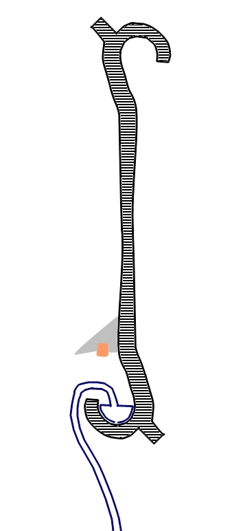
The
2C-beam may hang like this in an I-beam or truss (described
below).
The 2C-beam can be much thinner and lighter now when it
needn't function as a beam.
Switching Movable Beams Other technical matters for the 2C-beam
The I-shaped Beam – with one Rail
The optimal shape for a beam which has predominantly vertical loading, is, as is well known by structural engineers: the I-beam, which is tall, narrow and with right-left symmetry. In its most efficient form it has flanges at the top and bottom. Another improvement (when low weight is important) is to use a truss structure. This can be widened out from a planar structure to a space frame structure to the extent sideways-acting forces are expected.
This
S-shaped beam functions structurally as a flanged I-beam.
As it is
made of steel, it could also be given the track for air cushion
operation.
This beam is unsuitable for vertical wheels, as they
need too much space.
If the beam and the rail are produced separately, it is possible to choose between many different types of beam and rail. The size may range from the really small one which enables a beamway to use a car tunnel together with cars, and up to a large truss for long bridge spans.
Other materials than steel may be used for the beam. If the price is more important than compactness, reinforced concrete may be used, and this can usually be produced locally in suitable shapes, including more efficient truss structures. An important advantage of the truss structure is that wind can pass through the plate instead of destroying the beamway. But the lower part of the plate, upon which wheels run, should be compact and smooth.
If the beam is molded, it is easy to make its ends suitable for direct interconnection, and to imbed diagonal carbon wires whose tension may be varied.
The rail will, of course, not have its splices near the I-beam splices, and this will greatly increase the total beam strength and reliability.
Carbon is a very interesting material for beamway trusses, especially if nanotube structures can be produced. Future beamway truss production may be like this: Captured CO2 is used as raw material in an "inverted combustion" process. In a 3D plotter, carbon is deposited as nanotubes in a truss pattern, controlled by electromagnetic fields. Where compression resistance is needed, strong crystals are grown. (Bones get their strength by growing hydroxyapatite crystals where compression resistance is needed, and medieval bow makers used bone on the back, compressed, side of the bows.)
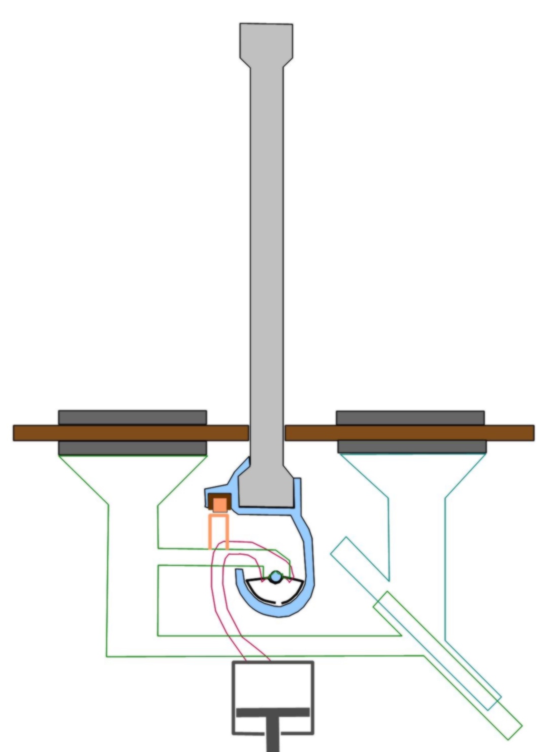
This
I-beam of reinforced concrete is combined with a steel track
beam.
Horizontal wheels with hub motors are used for propulsion,
but not for carrying weight.
Only
the lower part of this I-beam needs to be unblocked for train
passages, so the two adjacent I-beams of a double track line can
strengthen each other considerably with cross braces.
A double version, with two gutters opening towards the middle, (and a common power line,) will be useful for gauntlet stretches (bridge spans and tunnels) and bidirectional single track lines.
A beamway line with little traffic could have a single track if the trains were converted for reversed gutter in each line end loop: At a gap in the line, each microloc is rotated 180°. (The lifter cylinder rotates, but not the piston in it.) Cables down to the wagon could be continuous if the two line ends rotate the microlocs in different directions.
The air cushion unit in this design may be something like 120 cm long: a 50 cm long air cushion unit on each end of the air cushion axle (in the center of the gutter), and a bare 20 cm axle length in the middle, on which two mechanical subsystems (both only vaguely outlined here) grip:
The suspension (red outline) is attached to the top of the lifter cylinder, which enables active suspension. The piston in this cylinder carries this microloc's part of the train weight. A compressor (not shown) sends high-pressure air in under the piston – for contributing to lifting the train in a controlled manner. The compressor (which may be encased in a nacelle together with with the cylinder) also delivers air to the air cushion unit, so that this can slide through the gutter (the track). The suspension is firmly attached to the air cushion unit, so if the train swings to one side, the air cushion unit rotates with it in the circular profiled gutter and gives its air pressure force in the right direction.
The propulsion subsystem (green outline) is held up by the air cushion unit axle, but is held with its wheels orthogonally to the I-beam.
Stopping train pendulation is now very simple: Establish a mechanical connection between the penduling suspension and the stable propulsion subsystem. As they both meet at the air cushion unit axle, a friction clutch (or a non-friction equivalent) should there give a suitably strong connection between the two subsystems. The microloc's controlling microprocessor should monitor pendulation and provide some clutch connection each time the pendule movement approaches the equilibrium position. Or a pneumatic (or hydraulic) damper could continuously provide a damping mechanical connection.
Two horizontal wheels (with hub motors) are visible in the cross-section picture, but there may be two wheels on each side (superimposed in the picture). The wheel(s) on the right side can be moved down and away by means of the diaginal sliding mechanism indicated – or perhaps rather swung down with a set of parallell arms. The microloc (or the wagon, or the train) can then be lifted off the beam towards the left side. A microloc can be exchanged by a service vehicle on the adjacent track.
Having horizontal wheels, not carrying any weight, is unconventional. But these wheels are spared from orthogonal forces (along their axes) as well as forces from debris in their track, so they can run very fast. 250 km/h shouldn't be too hard to achieve. A contributing factor here is that the wheel diameter isn't limited by the space in the beam. If Protean hub motors are used, it should be more economical to use the standard version for cars rather than ordering a special train version. This model maxes out at 1300 rpm, corresponding to a wheel diameter of 82 cm for 200 km/h, or 102 cm for 250 km/h.
The wheels have three functions: Propulsion (with regenerative braking), stabilization and derail prevention.
Compact, steel-reinforced rubber should work fine on these wheels. This gives good traction, as well as quite little maintenance work. These wheels (and the whole propulsion subsystem) can be really light-weight. If some of this should fall apart, it has small consequences for the train operation.
A miniloc with some of these microlocs can have good pulling power even if it is light. This is because its maximal traction doesn't depend upon its weight, but upon how hard it can squeeze the wheels together.
Crossing in the same plane should be quite simple for I-beam based lines, as the train only passes the lower part, so most of the two beams – the upper parts – can meet in a solid X. The low I-beam can simply be missing; the horizontal wheels on a fraction of the train can do without this surface. The gutter can have short breaks for passing trains, as the sled (air cushion unit) will be long, almost 2 meters long, and should be able to cross a half as wide gap. (The mechanisms at gutter level, with green outline in the picture, could be made quite narrow and close to the gutter.)
Track switching can be done with movable beams, as is common for monorails, and this method is well suited for high-speed trains.
Air Cushion Microlocs: Independent and Co-operating
Some principles are common to the 2C-beam and I-beam varieties of air cushion hovering: The microlocs should be independent and co-operating, and the air cushion process should be adiabatic.
According to the microloc philosophy, each microloc should have full capabilities for hovering and propulsion. A central compressor may seem more economical, but this would make the air cushion process non-adiabatic.
Having this process adiabatic, means: The heat which is generated during compression is not allowed to escape, but it causes the air expansion in the air cushion to give more lifting power than if the temperature had decreased. Avoiding cooling is especially important in a cold and moist environment, where additional cooling would give problems with freezing where the air expands.
Adiabatic operation implies: short distances and short storage times for the compressed air – hence independently operating compressors in the microlocs.
But some redundancy is needed. A train shouldn't be disabled if one microloc's compressor fails. The suspension separation should be so small (e.g. 2 m) that adjacent suspensions (microlocs) can handle the extra weight. When compression fails, the piston in the suspension cylinder falls to the bottom, so this suspension stops lifting the train, and only the weight of the microloc needs to be supported. Small wheels at the ends of the air cushion pads can do this at low speeds. The air cushion pads might have vanes for passive air cushion hovering at higher speeds. But this means that trains using such microlocs can run backwards only at low speeds. Some microloc autonomy should be sacrificed, so that the microlocs to some extent can share compressed air. The simplest way to do this is: Make the air cushion units so long that they almost meet each other. Their ends should be telescopic, so that when there is high air pressure, the ends are pressed out, meeting and connecting with the neighbor, so that compressed air can be shared. This would probably not give sufficient lift for lifting the train, but at least the microloc can lift itself.
In case of total power loss, and vanes for passive hovering are unable to ensure hovering down to steel roller speed: The power cables for supplying power to the wagon are used for sending power from backup batteries in the wagon. This power is used for running the air compressors. Or power for the compressors is delivered by the hub motors during regenerative braking. The train will then slow down in a proper manner.
Passive hovering and compressor-driving regenerative braking are now two similar methods for converting kinetic energy into lift. If the vanes for hovering are inconvenient or inefficient, they may now be dispensed with.
Conclusion
The I-beam design seems to be the best one, due to its flexibility and simplicity.
Changes:
September 21. 2010: New article
September 27. 2010: New chapter: Air Cushion Microlocs: Independent and Co-operating
October 3. 2010: The chapter Air Cushion Microlocs: Independent and Co-operating is extended with power-loss info.
December 1. 2010: The power computation is extended with 10 and 12 microloc examples.