The
Beamway
by Olav Naess,
2006-2014
A
City Beamway
Metros
and Architecture
Scalability
The
Safety
Cargo
Additional
Passenger Wagons
Private
Pods
Mobile
Services
Running
(between) Hospitals
Post
Commuters
The
Disabled
The
Environment
Existing
Beamways in Germany
The
Main Points
Summary
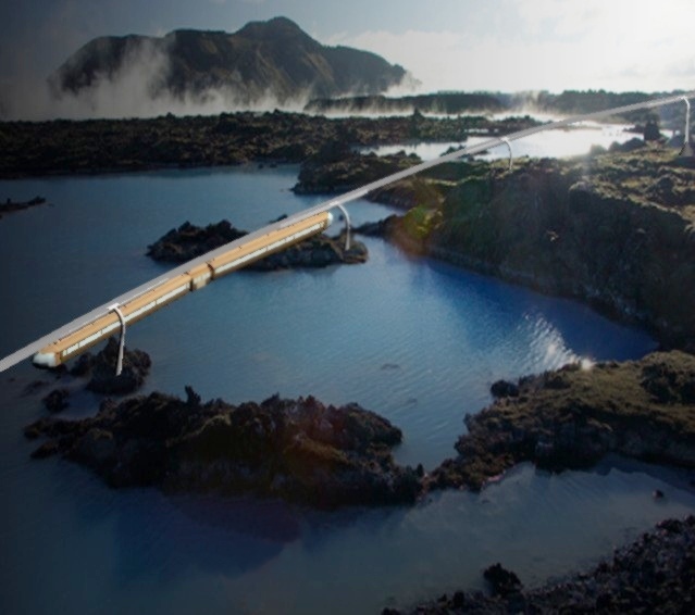
This is about the
question: Perhaps there should be railways for transporting people?
For transporting
passengers (with 6-8 tons/wagon), it is a very bad idea to use
conventional heavy rail (for over 100 tons/wagon).
A (correctly
weight-adapted) beamway should then be used. This is a suspended
monorail running along a steel beam. These trains can run above other
ground activities (road traffic, pedestrians, playing children,
wildlife, avalanches, untouched nature...). The beamway can negotiate
slopes of over 10%, and give a 99% reduction of ground razing,
barrier formation and snow problems.
This
is important for the environment.
Additional track
area will not be needed in difficult/congested areas, as the beamway
goes above roads – also across road bridges. If the beamway
tunnels run along road tunnels, free escape tunnels are obtained.
As
the beamway grips cabins at the upper edge, it can easily transfer
cabins (4-24 meters long) between ground positions, boat decks...
Such
cabins can be used for recreational/living
quarters, mobile services...
The
beamway can also move cars, boats,
cargo containers...
Suspended
monorails are now in operation in
e.g. Germany, but should be improved (for 200 km/h) as described
in this article, and with:
The beamway can
(with short wagons) be used in cities, also in old, compact cities:
No houses must be removed, no street or road be closed.
The
normal commuting radius may then exceed 100
km. The same region size will be achieved also for airports and
hospitals, into which the trains may enter. Medical personel,
patients and equipment may then be sent between hospitals
like with the latter's pneumatic tube systems.
Why Lightweight
Rail?
Traditional
railway is heavy-weight, designed for each wagon to carry 125 tons
(Wikipedia).
The real requirement for passenger, express and local trains is 6-8
tons, and such a wagon weights 40 tons. This is a tradition which is
based upon the assumption that flat ground may be appropriated and
reserved for the railway. Where this is possible, the consequence is:
All ground transport must be in one plane. In more awkward locations
(like coastal Norway) the consequence is: No railways at all.
Politicians
evaluating high-speed rail for passenger transport should have
experts on passenger transport. But they only have (or use) experts
on heavy freight, and these assume that their rail concept is
appropriate for transporting passengers, when less than 10% of the
weight load capacity is utilized. The consequences of this assumption
is not analyzed.
The minimum weight
for trains running on the ground was demonstrated in February 2007
when a train was derailed by snow masses on a Norwegian mountain
line. The train — called a Signature train — consisted of
motorized wagons, each with 72 seats and weighing 54 tons. A local
train expert told the media that he had warned against using such a
light train, as it could slide like a snowboard and derail. A heavier
locomotive, which could push an efficient snow plow, should be used
in front. In warmer climates, where snow masses may be disregarded,
trains must still be built to survive collisions with cattle and
other large animals, as well as crossing road vehicles. If the track
were replaced by a beam running 6-8 meters above the ground, resting
on pillars, both snow mass disturbance and collision danger would be
virtually eliminated, so now lightweight technology could be
employed. A positive feedback is encountered here: Rail elevation
enables light trains, and light trains are easy to elevate above the
ground. (Such positive feedback situations can create quantum leaps
in technology, and this effect seems to be effective here.) An empty
wagon for 70 passengers needn't then weigh 40 tons – perhaps
only 5.
The reduced weight
leads to improved fuel economy and reduced emissions, as well as
simplicity and reduced costs for bridges and other railway
installations.
Having the
lightweight rail "upstairs", enables it to be placed above
existing roads and road bridges. It can also take shortcuts over
rivers, lakes, agricultural areas, parking lots, garages, streets,
pavements... Complicated compulsory purchase processes may be
replaced by simpler economic compensations.

The Beamway
(a suspended train, running in a steel beam):
99 % less
ground razing and barrier formation
(Scenery
photo: Freephoto.com)
It is highly
unlikely that something will get in the way of such a train. It can
consequently run at high speed, also in densely populated areas. And
it can be driverless, the way the suspended trains in Dortmund and
Düsseldorf do. Low passenger capacity in each train may then be
compensated by frequent departures. It is better for the passengers
to have a small train each 15 minutes than a large train every hour.
The passengers may then choose between fast trains with few stops,
and slower trains with many stops.
When transport of
passengers (along with mail and other light goods) need only 1/15th
of the weight capacity, it should be clear that an
alternative rail type should be considered. If freight trains must
keep adapting to the needs of the passengers, the transport capacity
cannot be efficiently utilized. To upgrade conventional rail for fast
passenger transport can easily become more expensive than a separate
light-weight rail, so why settle for a compromise railway when two
efficient can be had instead?
The Monorail –
always Exiled to the Future?
The
monorail is a light railway running on a narrow-gauged track which is
on or inside a rigid beam. This means the track needn't be upon the
ground, but can run on top of poles, so that it doesn't conflict with
constructions, activities and the nature down on the ground.
Conventional railway, on the other hand, will normally require a
reserved area which can only be crossed by other traffic on certain
places. The train doesn't have to balance upon the beam, so this can
be narrow and thick (high). It can then really function as a
load-carrying beam. The lightweight rail will then become a monorail.
Monorails in general are thoroughly described here.
There are two main
types of monorails:
The
train straddles the beam, so that it is stable and secure against
derailing, by having each wagon's chassis divided in two by the rail
and stretching somewhat down on both sides of it. The beam of this
(type ALWEG)
prevent vertical passenger movement towards and from ground level,
so this kind of railway require elevated stations unless the station
areas are reserved for this purpose. Snow and ice may obstruct the
beam, and birds perching on the beam are likely to become massacred.
The train is
hanging under the beam. The wagons are hanging below 2-4-wheel
bogies (trucks) which run inside the hollow beam. Wagons (or an
elevator built into a wagon) can consequently be raised or lowered
with arriving or departing passengers. With a hanging train, the
passengers are not exposed to the sideways-acting forces they else
must endure when the train speed doesn't fit the banking of the
track.
Besides, a beam can hang under a simple row of cables
when the train is out of the way.
These advantages are the main
reasons for us to concentrate upon this type: the suspended beamway.
The
beamway we are going to discuss, is of the type SAFEGE,
a French design from the fifties. Such a railway was tried in France
about 1959-70 (and shown in the movie Fahrenheit 451), but wasn't
successful. The Safege technology was later sold to the Japanese, who
used it for some local railways. (See a movie cut here.)
The beam/rail
design is called SIPEM, and is developed by amongst others Siemens.
The
Swedish Swedetrack Systems AB has here
presented a description of their FLYWAY concept. My discussion and
ideas mainly take this description as the point of departure, but has
a different attitude towards the means of conveyance: Swedetrack's
FLYWAY-description is car-biased, while the present discussion is
bus/train-biased.
Car or Bus?
Visions about
future transportation systems often start with assuming that the car
is the preferred means of transportation, but regard the conveyor
belt principle to be needed for managing the flow. This is also the
point of departure for FLYWAY, which depicts and describes
essentially small passenger cabins. The largest cabins are for 32
passengers, but also these are treated like small private cabins: The
entire cabin is lowered whenever somebody is entering or leaving, and
such a bus ride would be quite annoying. Small cabins with 2-6 seats
pose the problem: Shall they be private like taxicabs, or are
strangers supposed to mingle? Such mingling would give personal
security problems in small cabins, but is safer in larger, bus-sized
cabins. It stands to reason that taxis are private, as they go all
the way to the destination building. But when the stop has to be
somewhere along the track – and perhaps only at designated
stops, it becomes meaningless – and perhaps dangerously
confusing – to privatize cabins. The fear of strangers is
intricately connected with society splitting and Hollywood
dramatization, but should not preclude future visions involving
public transportation.
Regardless of the
cabin size, the danger of vandalism should be taken into account.
Both personal and material security can be improved through video
surveillance, but it is of little value that a situation is
immediately perceived in a security central if it takes more than ten
minutes before somebody can act where the action is. Personel on the
train may be using the same video images, but if they sit in the next
wagon, they can be far more useful.
Visions of future
technology tend to be far more optimistic regarding human nature, but
nevertheless: I will assume we will need vehicles emulating
conventional trams and buses, and with a centrally positioned
conductor.
Transport visions
tend to forget an important point: That travellers need access to a
toilet. Also this calls for the bus size.
But
private cabins may be used for special purposes: Transport of
patients and medical personnel can be automatized and function like
the pneumatic tube systems in hospitals. And mobile
services should be able to have their service cabins dispatched
around in the beamway system. It is also useful to let the beamway
transport camping cabins to and from
camp sites, and transport boats
between storage and sea. Besides, wagons for mail
and other light goods could go along. In some areas, private
pods (cars/cabs) may swarm. This may occur in the same beamway
line system, provided there are enough sidetracks to prevent train
traffic delays.
Quite many (half)
private wagons may use the public lines if they are scheduled to move
in caravans.
It is very
important for beamways that the cabins will not be overloaded by
chaotic crowds (at rock concerts, sport events, ...). Here are two
ways to avoid this:
Use special
stations which have a solid platform immediately under the cabins.
If a cabin is overloaded, it sits down on the platform and stays
there.
The passengers
are admitted through a sluice system which automatically closes all
access during an overload situation.
The first station
type is suitable on special places (like end stations) where the
traffic is heavy, but leaves the problem with throwing out some of
the seated passengers. If the beamway contains an elevator, it will
be able to stop for arriving and departing passengers almost
anywhere, and at the same time have an excellent sluice mechanism
which automatically refuses to raise an overloaded elevator, or to
lift passengers up to a train which is becoming overloaded.
Such a sluice
would also make it difficult for terrorists to place their packages
and immediately leave. If all luggage items are registrated when
passengers are admitted, it should be possible to detect if anybody
tries to leave without all their luggage.
Container
Transport of People?
Transport
of goods became far more flexible and efficient after the
introduction of intermodal
freight transport, which is based upon use of containers, easily
transferred between different means of communication.
It is now natural
to ask: Could similar efficiency gains be obtained with passenger
transport? The concept of intermodal passenger transport
implies merely a short walk between the modes of
transportation.
The main
advantages would be:
Better travel
opportunities for disabled people
Less fuzz with
luggage handling
Saved time –
the slowest passenger determines the delay
Repeated
passenger controls are avoided
Most passengers
would undoubtedly benefit from using their legs, but they should get
opportunities for this in other ways.
Transferring
containers involves slow operations with cranes, and stacking the
containers in ships and harbors. Passengers can't be subjected to
this: For passenger cabins, smooth and swift transfer is imperative,
without cabins dangling under cranes.
Transport by both
ship, railway and road imply placing the cargo on horizontal
surfaces, so each transfer involves lifting the cargo, moving it to
another surface, and putting it down there. There is a need for a
means of conveyance which can deliver cabins from above and (with
minimal movement) directly to a receiving surface, and vice versa.
This is the way
the suspended train of the beamway operates, and that is one of the
reasons we will take a closer look at it.
Recommended
Beamway Design
The main
principles for the recommended beamway design will consequently be:
Start with the
FLYWAY design, which states that an 80x80 centimeter beam can carry 7
tons if the distance between the poles is 30 meters. Then add the
following set of improvement proposals:
Let the beam go
from pole to pole without a joint. The joints should come at the
poles, where it is easy to place heavy and balanced splints –
fortifying side plates which go along the beam, strengthening it like
the splints placed along a broken leg. If they fortify really
efficiently, we could, with 20 meter long splints, sort of have 20
meter wide poles, so that we could have one pole every 50 meters
instead of every 30. It may, however, be more realistic to assume
that this pole widening is done only half ways, so I will tentatively
assume one pole every 40 meters.
When the beam is
forced to be horizontal (or with another precise inclination) near
the poles, it will not be able to sag much down near the middle.
Besides, the whole beamway structure is strengthened and able to
withstand e.g. emergency braking.
It may seem
strange that the FLYWAY concept, for up to 7 tons, can be used for
long trains with several times the weight. But a long train will have
only a small fraction of its weight in the weak central part of the
beam, especially if it is designed to function as a movable beam.
This beam will have a stiffness which adds up to the stiffness of the
beam, so that mainly the poles will get the weight of the train.
The Poles
The poles carry a
bracket or a small platform which on its lower side (inside) carry
the ends of the half-beams, and a splint on the sides of a beam
joint. The beams are not assumed to have exactly the correct length,
so there must on both sides here be a holder for a small rail piece –
e.g. 1-80 cm. Some places a service platform may be needed, so the
gap between the beams must here be so wide that the bogies running on
the track can be lifted out.
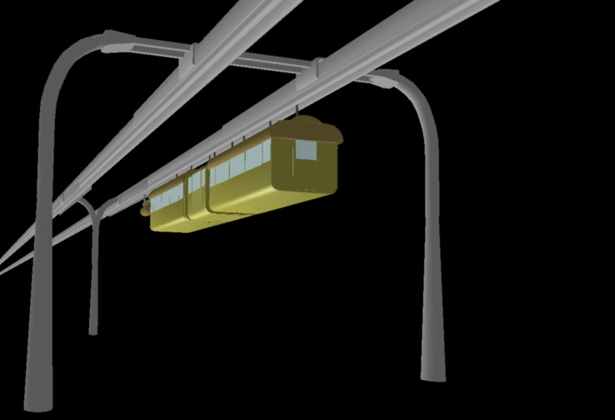
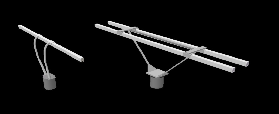
A pole should
be prepared for expansion from single-tracked to double-tracked
operation, carrying either simultaneous traffic in both directions,
or letting parts of two different lines follow each other for a
while. The pole should then on its backside be able to carry an
additional beam holder – seen in the background here – so
that the pole has traffic on both sides. Another alternative is that
two poles are mounted with meeting beam holders, or a long common
beam holder – in the foreground here – so that the whole
assembly form a bridge which can carry a double track beamway along
and above a road.
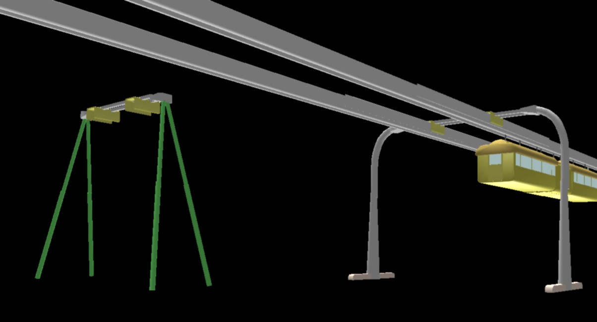
If the two
poles have side support legs as shown here, a stable and movable
stand is obtained. This enables provisional beamway lines, which may
e.g. be moved to the side if the beamway gets its own tunnel.
It should be
possible to attach the beamway to the facade of certain structures
like large garage buildings.
A line of
windmills should also be able to function as a row of beamway poles,
and the two systems may cooperate about power lines.
The Beam
Beam joins should
not occur between the poles, only at them – between the
splints. But a 40 meter long beam would still not be too
unmanageable, as it is divided in three parts lengthwise: Two
C-shaped half-beams, both symmetric and exchangeable, supplemented
with a connecting and protecting plastic part which contains the
power line.
As the power line
is surrounded by iron, a good shielding of the electromagnetic fields
is achieved, in contrast to the freely hanging power line of
conventional railway, which causes strong electromagnetic pollution
of the environment.
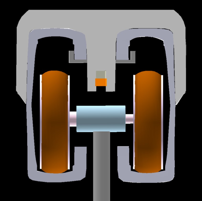
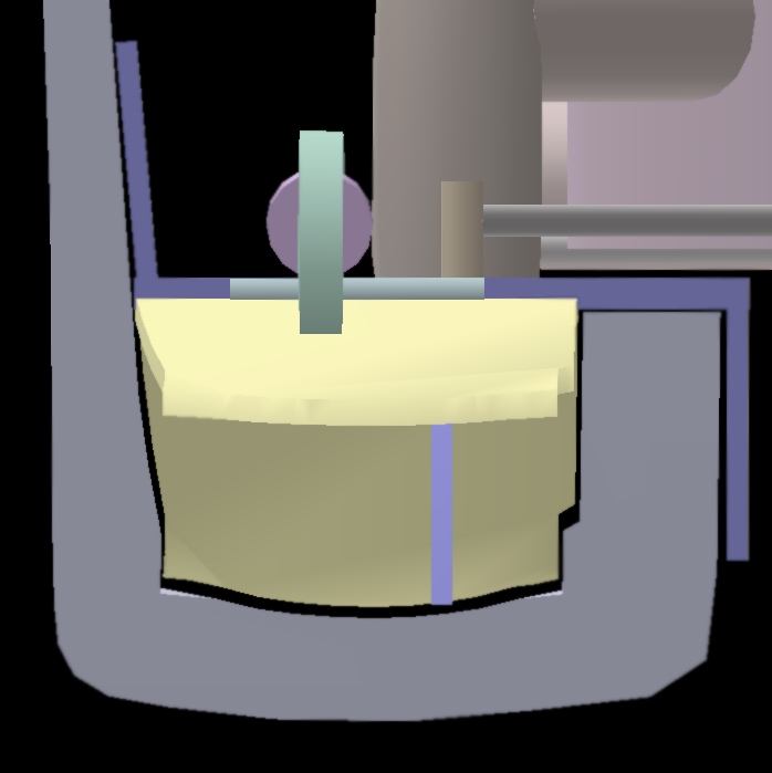
Section of the
2C-beam. The power line is in the middle.
Left: We see how the
wheels (for slow local trains) run in the two C-shaped half-beams.
Right: Air cushion drive (for high-speed trains) with the same beam.
The air cushion is trapped under a steel lid (blue), and between two
valves (yellow). The front valve is open. The rear valve is closed,
so the train will be pulled in that direction. (The air cushion unit
gets pressurized air from a compressor loc – see under The
Locomotive below.)
Each C-shaped
half-beam will be only about 30 cm wide, and can consequently at the
line construction site be given the moderate curvature needed for
turns on high-speed lines (with increasing/decreasing curvature
before/after turns), as well as the twisting needed before and after
graded turns. If conventional SIPEM beams were to be used, they would
be about 80 cm wide, and far more difficult to bend and twist. If
they had to be factory ordered with specified combinations of
curvature and twisting, the manufacturing, logistics and line
modification operations would all be very problematic.
Having the power
line surrounded by iron, will greatly improve the shielding of
electromagnetic fields emitted – in comparison to the strong
electromagnetic pollution caused by conventional railway power lines.
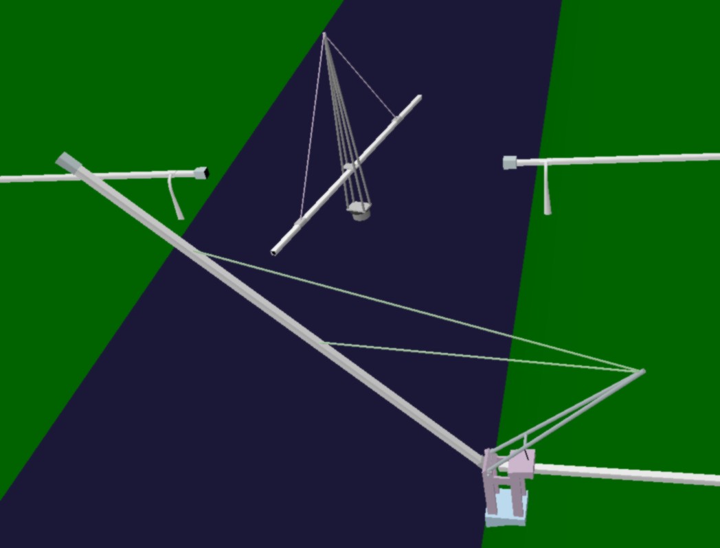
When the poles
have been erected, the beamway could be built without local ground
support: The half-beams are transported along the finished part of
the beamway. At the end of the stretch, hangs a crane boom which
lifts a (left or right side) half-beam up to proper alignment, being
partially affixed at both poles. This operation is repeated for the
other half-beam, and workers on or at the rear and front poles fasten
the half-beams more thoroughly. The crane boom is then moved forward
on the new beam stretch, and the operation is repeated.
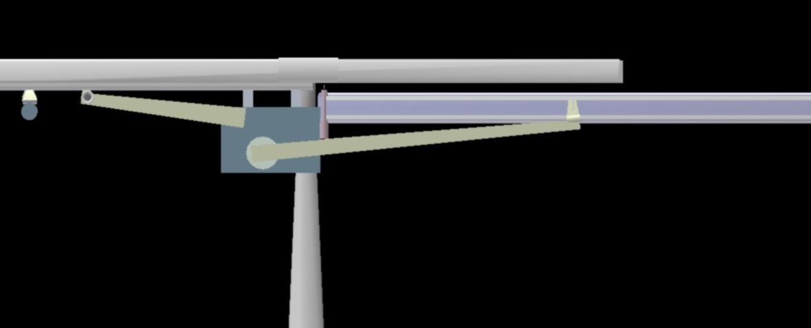
A half-beam is
here lifted up to its correct position
(Detailed
description here)
If
the monolithic SIPEM beam were to be used, a beam length would be so
heavy that beamway lines could have been constructed only on sites
accessible to heavy mobile cranes. Or the beam would have been
weakened by many splices between short beam stumps. The 2C beam can
be without full splices, as there can be many meters between splices
of staggered half-beams. (More
details here)
The Train
The FLYWAY concept
is about city traffic, and prefers small private cabins –
automated taxis. We will here consider another use of the beamway:
trains, capable of replacing passenger planes on distances up to
3-400 km, so the speed should be at least 200 km/h. (And the fast
trains are needed only for light-weight transport, not for the 10-15
times heavier cargo).
Heavy trains with
the same top speed will actually become slower due to low
acceleration and slow movements in station areas and other difficult
areas.
At high speeds,
the beamway has the significant advantage that it can easily get a
straight path without requiring a brutal leveling of the ground. And
in the vicinity of the train is nothing but a smooth metal surface.
The size and
weight of the train, however, is a formidable challenge for a beamway
dimensioned for beam loads up to 7 tons. The key to designing real
trains is: to distribute the weight over a longer distance. The
starting point for the train design is: a small center wagon which
essentially is an elevator, so that arriving and departing passengers
can be transported vertically – about 5 meters – between
the ground and the train. Each end of the center wagon has a door
leading to a passenger cabin. For tram emulation the cabin will be
bus sized (8 meters), for train emulation the cabin will be train
wagon sized (24 meters). The passenger cabins may very well have a
generous seat separation, and may be sitting 2+1 abreast, so that the
weight is well distributed along the beam. (The length will still not
approach the walk through the gate corridors of an airport!)
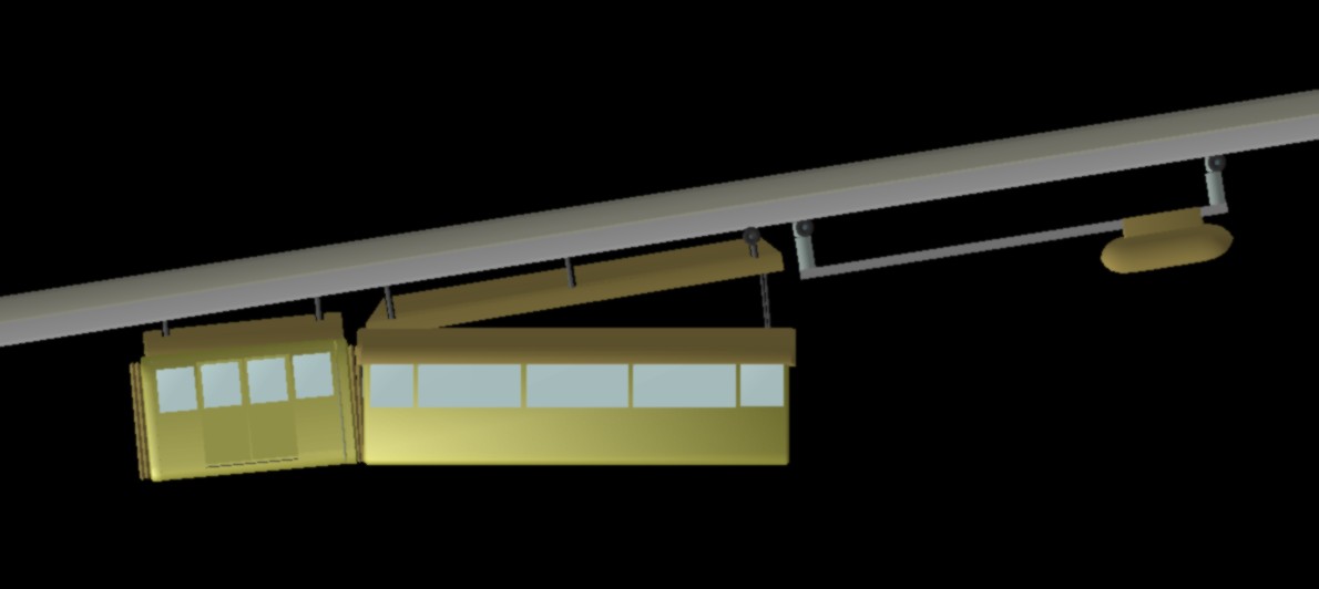
The locomotives,
with light electro motors, can be several meters in front of and/or
behind the passenger wagons. (Such a miniloc is shown in the yellow
train depicted below.)
The train will now
become so stretched out that only a small part of it weights down the
weak mid part of the beam. A special trick for spreading the beam
loading additionally: The center wagon pulls the passenger cabins at
floor level and pushes them out at roof level.
Hopefully, the
same beam type can be used for trains and trams, so that they only
differ in the minimum curvature radius. It may be wise to let the
train have a turning loop around the city center, so that the
passengers can choose in which city part to go on or off. Or the stop
for the long-distance train can be near the stop for a city line. Or
the long-distance train can exchange a short second wagon with a city
train.
The fast trains
require larger wheels, and there isn't room for more than 50-55 cm
wheel diameter in the beams. This could give 120, perhaps 140 km/h,
according to FLYWAY. This is OK for local trains, but not for long
distance trains. Even though the wheels can run somewhat faster in
our smoothly curved 2C beam, one should from the beginning be
prepared to go for more exotic technologies like air cushion hovering
and maglev (magnetic levitation). This needn't mean trains without
wheels. A hybrid technology may be used: The weight load on the
wheels are gradually decreased by 80-90 % as the speed increases, so
that wheels can be used at higher speeds.
An air cushion in
the bottom of the beam takes over most of the weight load, and it
stabilizes the wheel between the side walls. This cushion can be
created by a compressor (in the grey nacelles located between the
wagon roofs and the beam in the picture below). Or the cushion can be
created by passive wanes leading the air towards the bottom and side
walls of the beam interior.
These
possibilities are more thoroughly discussed elsewhere,
but we may say that those working with these technologies for surface
trains, should be envious of the beamway conditions: automatically
balanced light-weight trains at a large, clean iron surface, going
above the snow and debris of the ground. Those now developing
hovering (maglev) trains are doing a grave mistake by taking
conventional heavy railways as the point of departure – without
having a need for heavy transport. It may seem natural to vary one
factor at a time, but now a double innovation is required.
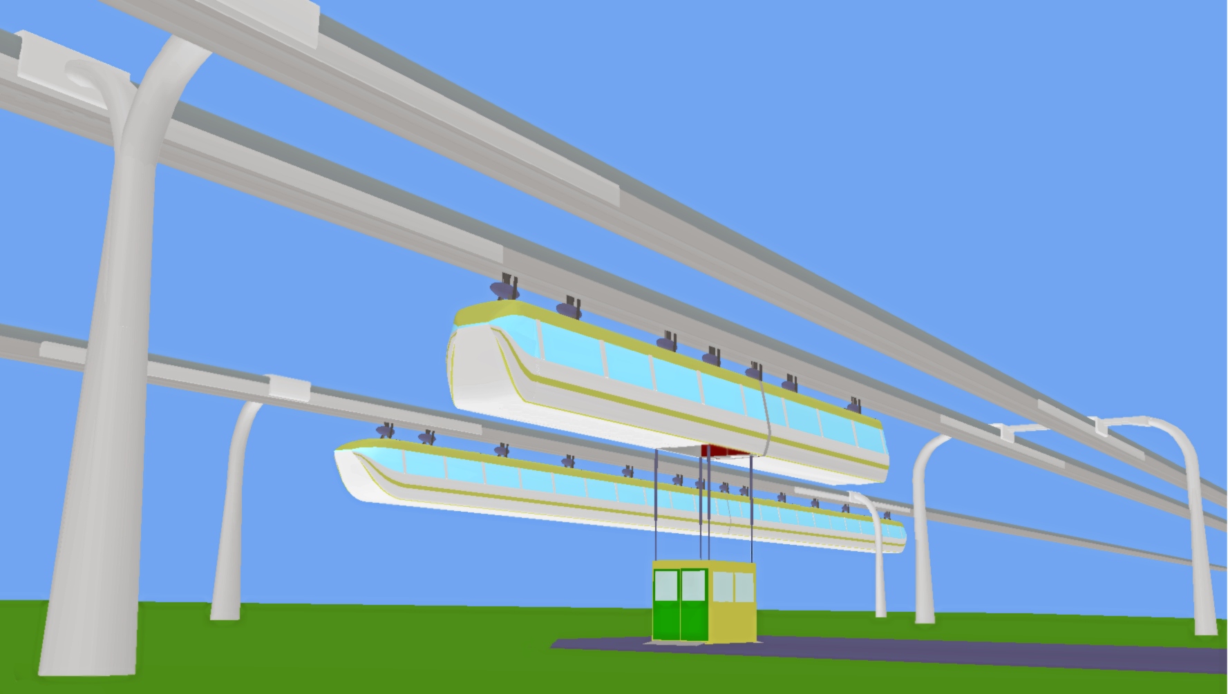
Local and
long-distance trains – both with an integrated elevator in the
front wagon. With this elevator, the doors leading to the cabins are
also used down on the ground. Passengers enter through the front door
(green) while those leaving use the back door. This efficiently will
largely compensate for the elevator delay.
Threshold ramps for
wheelchairs are pushed out under the doors.
These trains have hub
motors in all the wheels.
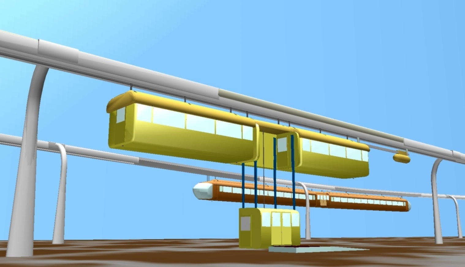
These
trains have exchangeable cabins (lowerable and raisable below those
funny hats), as well as a separate elevator module between the
wagons.
This elevator uses a side door, so that passengers can
enter directly if train and platform are on the same level. A
disadvantage with side door use is that any train penduling threatens
the passengers' feet.
A built-in threshold ramp might have been
used here, too.
The Center Wagon
This consists
essentially of three or four walls and a roof, as well as an elevator
filling the space between the walls. The elevator is for the yellow
train above depictet as hanging from a single cable coming out from
the middle of the ceiling, and the elevator movement should be guided
by vertical telescopic rails hanging from the ceiling, going down
through vertical ducts in the elevator walls. If there is a cable in
each of the telescopic rails (white trains depicted above), the
elevator may be lowered 15-20 meters for emergency evacuation, and
yet ascend again with properly collapsed rails.
If the elevator
has a side door, a conventional station flatform on the train's level
may be used, so that passengers can come and go quickly –
without elevator movements. The problem with this is that the
overweight-preventing sluice mechanism given by the elevator is lost.
A solution for this is to provide high traffic stations with an
antechamber (measuring the total passenger weight, and having
automatic doors) at each train door position. This antechamber will
then provide an alternative sluice mechanism. (The conductor may at
low traffic levels choose to leave the door open out there.)
With this external
sluice, the beamway will give as rapid passenger exchange on stations
as conventional trains do, and consequently as large transport
capacity if the latter were trying to give seating for everybody.
(But an elevator with entrance and exit on opposite sides might be
just as efficient.)
The thick back
wall of the center wagon should contain the elevator motor and an
emergency battery or generator capable of running the elevator for
emergency evacuation, and also be able to move a train somewhat in a
powerless area.
The central
element (regarding costs and operations) is the conductor, who sits
in the elevator.
The tasks of the
conductor are to:
check that the
passengers are ready to take the elevator to or from the train (–
and that they don't sneak past ticket vending machines), must pay
cash, or are walking towards the elevator
give the
passengers information regarding this strange system, including how
to pay and to get to the right destination
help disabled
passengers a little
take care of
parcels to be picked up at another stop. (Such flexibility is
natural in rural areas. This includes informing about who have been
observed.)
be a guard, and
at least warn and report troublemakers
deal with truck
drivers, construction workers and others with traffic-disturbing
activities
decide the speed
of the train if the conditions are too unusual for the automatic
control
The Propulsion

The train may have
a locomotive fore and/or aft. The advantage of this is that the train
weight can be distributed over a long distance. The picture shows a
locomotive with a large motor which can be displaced remotely. But
this will block passenger evacuation through end doors of trains
stuck in tunnels, under bridge spans, etc.. The most elegant solution
is to let an electric motor constitute the hub (and most) of each
wheel. This will optimize hill-climbing and acceleration, as all the
wheels will be pulling.
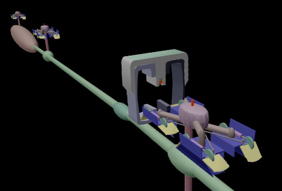
For high-speed
operation – no wheels, but the train slides on air cushions:
A
compressor “locomotive” (left), and one of the hovering
bogies with four air cushion units powered by high pressure air
coming through the tube.
The compressor hangs under two such
bogies.
Propulsion is obtained by opening valves backwards.
Several propulsion
technologies, using the same beam and mostly the same trains, are
available. The most important alternatives are:
Running on
wheels, with ordinary electric motors.
Like 1, but
airfoils near the wheels can lift partially, so that at least half
the weight can be relieved off the wheels.
Such air-surfing away
from vertical beam walls will keep the wheels in position in their
tracks. Wheels can thus be used at higher speeds.
Compressor-driven
air cushion surfing with high-pressure cushions above the beam track
and low-pressure cushions below the beam. This enables strong
resistance against penduling if the pressures can be reversed on the
side in danger of being lifted.
These may be
combined in various ways by combining bogies or bogie parts, and by
combining different elements on one bogie.
But one
combination – alternatives 1&3 – should be emphasized
as an optimal compromise, as it gives high speed on simple beamway
lines, that is lines not equipped with trainpulling equipment
(maglev, linear motors):
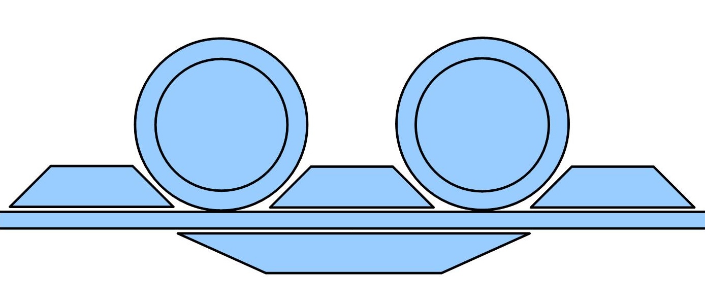
A combination
drive for quite high speeds – at least 200 km/h: Two wheels are
combined with three air cushions above the track and one (mostly
sucking) below. There are electric motors in the wheels.
The air cushions
above also act against the side walls, so that the wheels are not
stressed by forces from the sides.
This combination
is programmed so that the lifting force from the air cushions always
are kept so low that the wheels can give the traction needed (or
regenerative braking, which receives the braking energy). At high
speeds, the need for traction decreases, even though the power level
(i kilowatts or horsepowers) is high. As the wheel stresses are
reduced – by perhaps 80-90 % – wheel traction can be used
at much higher speeds – probably well above 200 km/h.
The wheels give
speed control. This means the train stands completely still during
stops in wind or in a hill, something likely to cause problems in
connection with air cushion drive.
Stabilization
against pendulation implies: Fast-acting valves reverse the air
cushion pressures on the side about to be lifted by a wind gust.
Simple, strong
wheels of steel or compact rubber can now be used without the
disturbing vibration forces. (The wheels are not to transmit forces
for emergency braking. This is done by mechanisms pinching the edge
of the beam.)
The compressor
creating the air cushions hang below, at the wagon suspension rod.
There may be one unilateral combination of wheels + air cushions (for
the left or the right side) for each wagon suspension, but perhaps
rather a bilateral combination, so that pendulation can be controlled
at each suspension.
Every suspension,
with its mechanisms, will then become a complete propulsion module,
an exchangeable microlocomotive which could have run alone, so that
the wagon only need small motors for displacing the suspensions
sideways.
These prospects
are more thorougly discussed elsewhere, but it should be said that
those who work with developing such technologies for ordinary trains
(running on the ground) should envy the beamway's conditions: well
balanced lightweight trains at a large, clean steel surface, above
the snow and sand of the ground level. Those now developing hover
transport (with magnetism or air cushions) and without a need of
handling heavy transport, err seriously when they take heavy rail as
the point of departure. It may seem natural to vary one factor at a
time, but a dual innovation is now needed: both suspended rail and
hovering.
Traffic Routines
The control system
can control access for the (not unusually audacious) passengers, and
can refuse to transport passengers up if the elevator or train is
getting overloaded. It can also detect obstacles and stop for them.
For local transport, unmanned operation may be feasible. Every second
departure, for instance, could be unmanned – for subscribers
who feel secure with the system.
As the beamway
system simulates scheduled buses instead of a stream of private cars
(the FLYWAY attitude), side beams (for passing a stopped train) will
not often be needed. The standard operating mode could be that two
trains start together. The first one is a direct train with few
stops, and the second one stops at many places. When the direct train
is about to overtake the other, the two can swap roles at the next
end loop passage.
A train's two
passenger wagons could be assigned to two branches of the line. When
the train comes to where the line splits up, one wagon can be
delivered to another train on one branch, while the center wagon with
the other passenger wagon continues on the other branch. If the lone
wagon has a motorized bogie, it should be able to run on its own for
a while as long as no stopping is required.
Many Kinds of
Stops
A beam train with
elevator could take passengers on and off almost anywhere, and in
special cases like ambulance transport (perhaps to a side track into
a hospital) this flexibility may be useful. But for practical
reasons, designated stops will probably be chosen – at least on
crowded places. The elevator will of cause detect people if it
approaches them from above, so it should be less dangerous than the
tram so commonly seen in pedestrian precincts. A simple and practical
solution could be to let the elevator go down towards a lawn, a
flowerbed or a lawn, while the passengers go up on a 30-50 cm high
ramp which will divert the stream of passers-by. If the elevator can
push out a foot board, wheelchairs can roll right in.
The train should
be able to start running while the elevator is going up ( – and
the elevator shoud have a few folding seats). Conversely, the
elevator might start descending while the train is slowing down at a
stop, but that may be to demand too much discipline from the
passengers. Some seconds will be lost if the elevator descends while
the train is standing still, but this is little compared to the
delays a bus suffers while its driver sells tickets.
The beamway could
visit many unusual places: the deck of a boat, a stadium stand, the
gate corridor of an airport, or the balcony of a closed-off area.
Some kinds of stops may be used only during special arrangements, and
then tickets may be sold or checked on the train. Ticket holders
could be admitted to one cabin, while ordinary travelers use the
other, so this will be closed when the train stops at the site of the
event. On an airport train, the cabins may be assigned to domestic
and international travelers, or for checked-in and not checked-in..
A City
Beamway
The
beamway doesn't displace other forms of traffic, and should be so
cheap to build that also smaller cities and towns can afford to think
line networks and branching lines instead of just one or two lines.
No
matter how congested the ground traffic is, the regularity and
reliability of the beamway will not be affected.
The
beamway can easily be built with a loop through a destination suburb,
even if the streets and buildings are old, so it will not lead to
dense spots of built-up area like a conventional metro does. I must
say it is appalling to see how local politicians assume suburbs will
concentrate around metro stops. This metro is then a Procrustean
line.
Correspondingly,
the city area should have an end loop which covers the most important
destinations in the central area. Having to regard the city center as
a point, is a sign of failure.
It can be a
dilemma for the city planners to choose: Should we have a small
central ring which becomes a suitably diffuse end stop, or a large
central ring which in itself becomes a useful ring line? It may be of
interest to have both. The two rings needn't be very different if
they are both single-tracked, running in opposite directions.
A beamway line's
poles may be freely standing racks, and then the line will be
reconfigurable, e.g. for a temporary line. Nice to have during events
like olympic games.
Metros and
Architecture
Metros (subways,
undergrounds...) are characteristic of large cities, and they are
difficult to scale down for light traffic. If we consider the space
requirements of a metro station, one major cause of this becomes
evident. A station for four tracks, each 2.5 meters wide, might need
2 meter wide platforms on each side of a track, plus 2 meters for a
stairway and elevator for each single or double platform. The minimum
station hall width will then be 10 meters for 4 tracks + 16 meters
for 8 platforms + 10 meters for 5 stairways = 36 meters –
multiplied by perhaps 30 meters for giving access to a few wagons.
This amounts to over 1000 square meters, and in addition comes a
crossing corridor above or below.
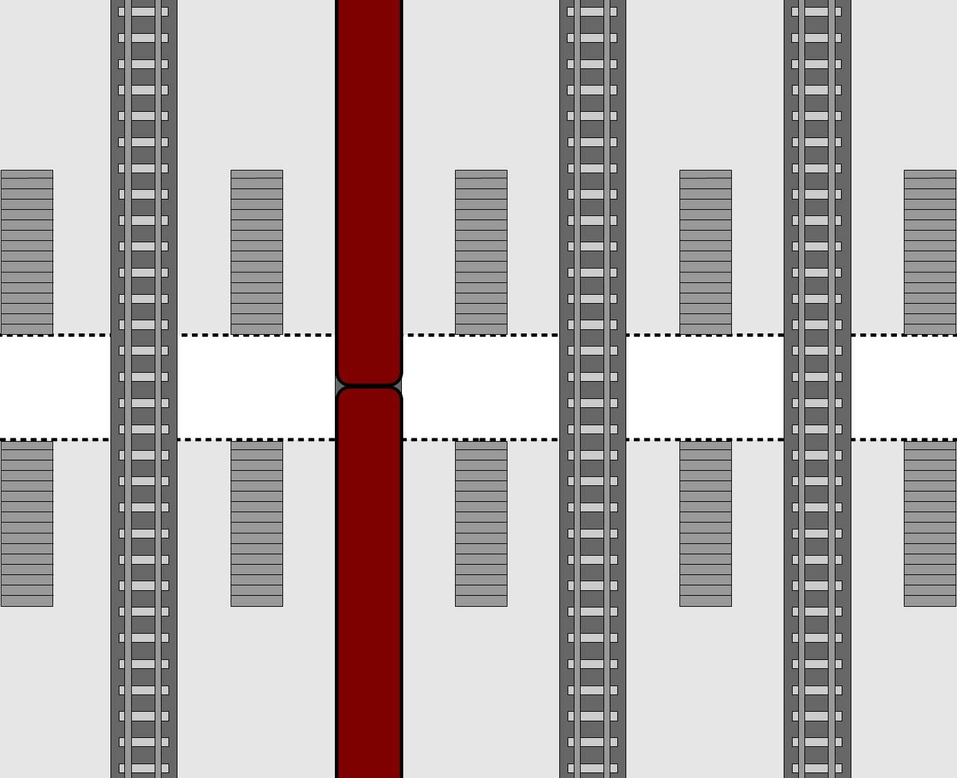
A
conventional station for four tracks, with one train present.
White:
A crossing corridor below or above.
A pair of stairs can have one
escalator and one ordinary flight of stairs. Besides, an elevator
will probably be required for each platform. It can be situated
between the stairs and make the corridor awkwardly narrow, or it can
be beside a flight of stairs and increase the station width by five
elevator widths.
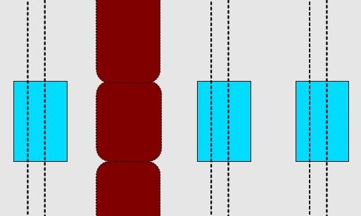
A
corresponding station for beamway trains having elevators.
The
blue rectangles are ponds reserving the areas for train
elevators.
The part of the hall in the upper part of the picture
is for departing passengers, the lower part for arriving.
If beamways were
used instead, stairways, escalators and elevators were not needed in
stations. With 3-3.5 meters of width reserved for each track, and 1-2
meters extra on each side, the hall might be only 13-18 meters wide.
With only 3 meters of the train length coming down in the hall, a
room as short as 8-10 meters could be used. So the beamway station
needs only about 15% of the normally required station area. And it
might be a few floors up in a building. (The trains would take 3-4
meters extra hall height, but this is only empty volume, without
construction complexity.) Besides, much space is saved in the
environment due to the short transition between parallel tracks and
multilevel, strongly curved tracks spreading in the environment.
Actually, the
space savings would be still greater if two lines crossed at a 90º
angle in the station area – in the same plane, but with trains
scheduled not to meet. The passengers would then only experience
that the doors were slightly displaced. Also conventional trains
could have stations at such a crossing, but this would result in
platform islets hardly permitting more than one train door to be
used. Hence the complex multi-level design of conventional stations
having crossing lines.
If beamway trains
were to cross in separate planes, the upper one would need a 6 meter
high elevator or a one meter high platform with ramps.
Every 2x3 meter
large elevator could go down to an equally large depression in the
floor, containing something like round rocks, flowers or shallow
water. If the elevator door leading to the front wagon were used as
entrance, and the door leading to the rear wagon were used as exit,
the passenger exchange would be so rapid that most of the time spent
on elevator movements would be regained. (In such a hall, the trains
could go just 2.5 meters above the floor.)
Such an elevator
might take 20 persons, so if more should want to enter or exit at
once, the small scale nature of such transport would become evident.
But the savings in space and other resources would be dramatic, while
the lacking capacity would be more moderate. And capacity can be
increased in various ways: The automatization potentials of the
beamway can e.g. make higher departure frequencies feasible. The
automatization potentials are related to the increased safety, as
people are unable to enter tunnels and tracks.
As long as the
trains go only in tunnels, the beam can be mounted in a very robust
manner, and the occurrence of many standing passengers is ok. The
sluice function of the elevator will then not be needed, so people
may also enter trains through simple stairways standing between the
trains.
Concentration of
the passenger stream in a few elevators permits use of conductors –
for improved service and security, as well as new operational
possibilities, such as sale or control of tickets to events to which
the train may go.
Beamway tunnels
can easily also be used for other traffic or transport if the
diameter is sufficiently large. Such combination use becomes more
difficult if conventional rail is used.
A beamway station
can be a few floors up in a building. As this railway type goes in
the upper floor above ground activities, architects and community
planners should operate with an expanded floor thinking, including
not only rooms, but also traffic and nature.
The old paradigm
was: All ground traffic had to be in one plane – shoehorned and
axed. The new paradigm is: The light traffic components should float
up to the surface – in the upper floor – where they, as a
beamway system, can be organized with a superior efficiency and
safety. Also natural activities, with pedestrians and animals, fit
into this multi-floor structure. Perhaps not so much under buildings,
which block much light, but at least under beamways.
Future planners
and architects will find it natural to plan non-blocking railway
lines through buildings, combined with small station rooms near
sidewalks, as well as in airports, hospitals, stadiums, etc.
Scalability
A
rail system should be scalable,
so that it can be used both in low traffic areas and high traffic
areas. It is common that rail systems (especially monorails) are
designed for large cities, and consequently get bad scalability. The
present beamway system is well suited for sparsely populated areas
(it scales down), mainly due to the built-in elevator, which
eliminates the need for station buildings. And even for quite high
speeds, the track needn't supply pulling force. This gives good
scalability, as it is easy to scale up by using a double-track line
and short departure intervals.
Beamways use
little energy and low power supply voltages. At about 1000 volts,
standard electronic components can be used, and hub motors are now
being mass produced for cars.
If trains become
cheap, backup trains may be kept ready at various places. And beamway
conductors (local housewives on part-time assignments?) will be far
easier to find than skilled train drivers.
Where can the
Beamway go?
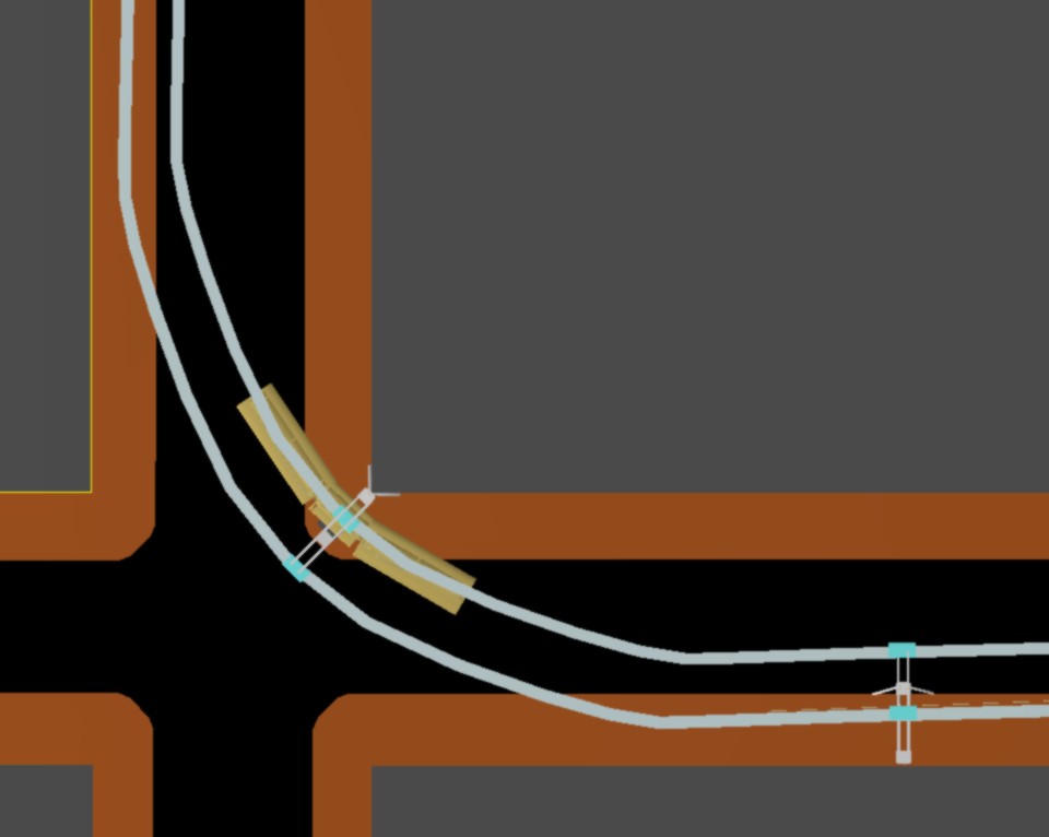
In city
streets:
Far greater radius of curvature (and absence of
obstacles) enable far higher speed
It is simplest to
let the beamway follow a road – at least as long as this isn't
crossed by bridges. If the road goes in a tunnel, the train can go
slightly above the road and behave like a bus, but the beam will
demand an extra meter tunnel height in order not to be in the way for
high vehicles. It shouldn't be too difficult to cut a groove for the
beam in the tunnel roof. Having this beam in a road tunnel, has
important safety potentionals: Remotely controlled beamway vehicles
(with backup batteries) can be used for firefighting, rescuing
people, or pulling out cars.
It may be found
advantageous to give the beamway its own tunnel immediately beside
the road tunnel, as this could also serve as an emergency exit for
the road tunnel, and a beamway tunnel will be much simpler and
cheaper than a road tunnel. It may in such situations be smart to let
the beam near the tunnel area be carried by freely standing racks
which can easily be moved to the new route.
The self-extending
beamway described above – lifting half-beam after half-beam
into position – can also save time and money during tunnel
construction. A tunnelling machine will then go in front and excavate
a round hole with a diameter < 4 meters. In the rear, the beamway
will be built by mounting half-beams each time a gap is created
behind the steadily advancing machine. Immediately behind the
tunnelling machine, a special slurry material remover will transfer
the excavated masses to wagons moving it to e.g. a bay crossed by the
beamway.
The beamway has no
need for its own bridges like conventional railways do: The beam can
be retrofitted on an ordinary road bridge.
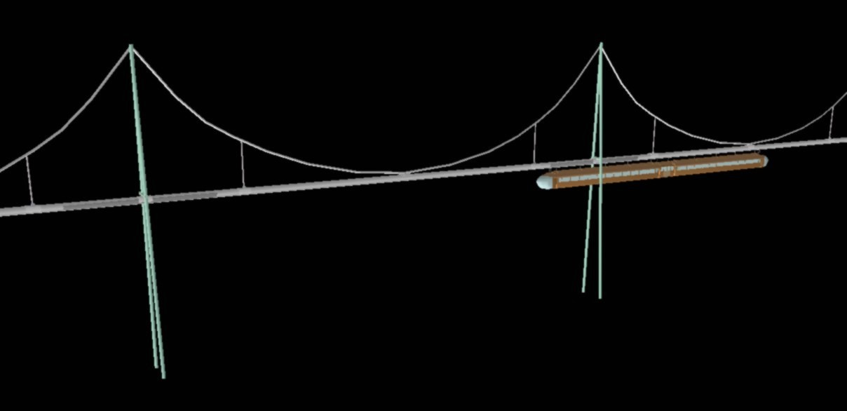
If the beamway
is to get its own bridge, it can be just a beam under a simple cable
span. The poles are now replaced by suspended beam-holding
brackets.
Perhaps the tower-building merely implies erecting
standard steel profiles?
- And building a bridge simply implies
hoisting up something assembled down on the ground/barges?
These bridge
types can be opened
More (shorter)
turnable bridges
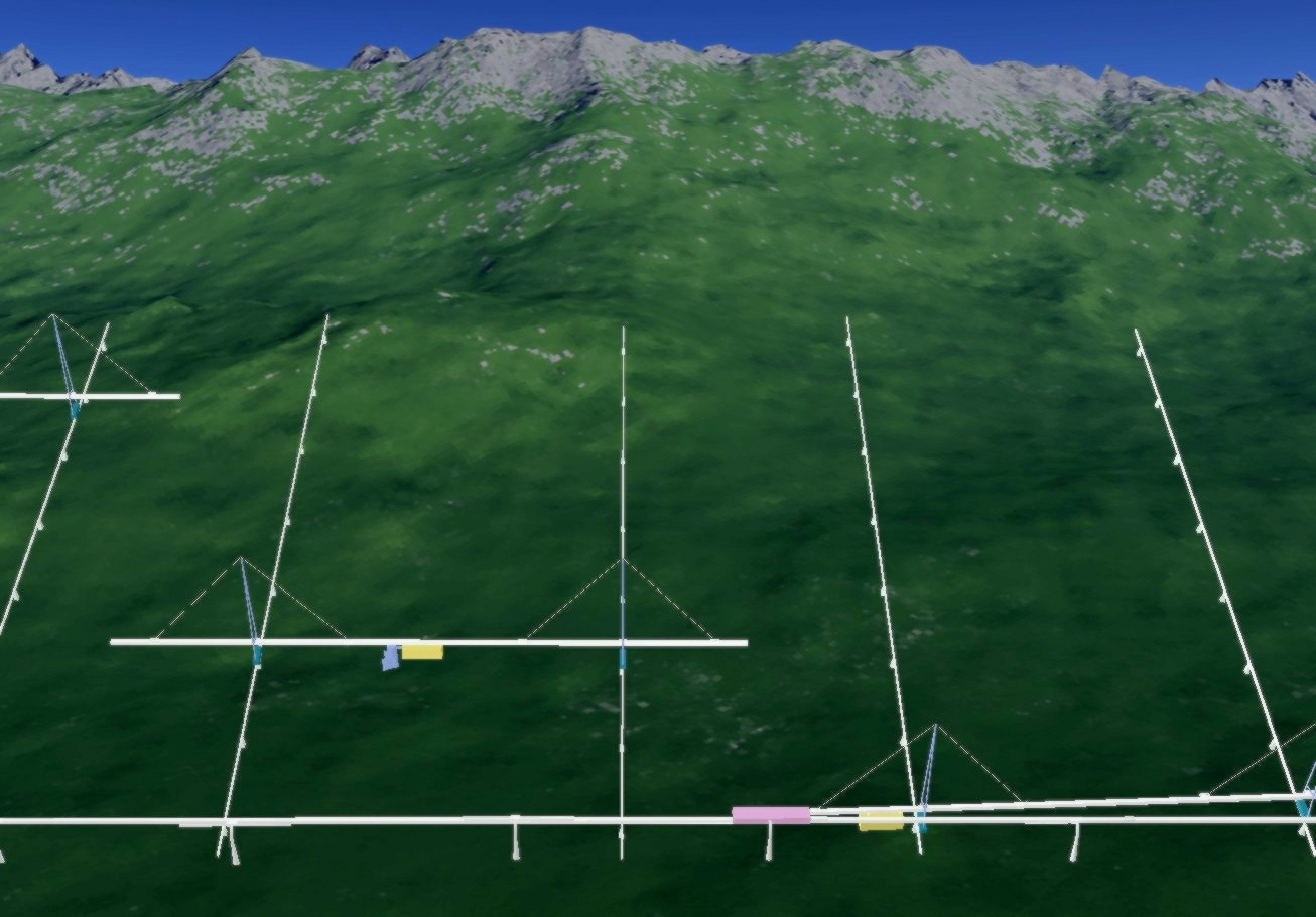
Agriculture
– particularly energy crops:
Harvesters and other machinery
can cover the fields by moving like beamway trains on beams which can
move sideways on a very wide “conventional” railway
track.
Containers go out with the crop and in with fertilizers on
the external line in the bottom of the picture. (More about this
here.)
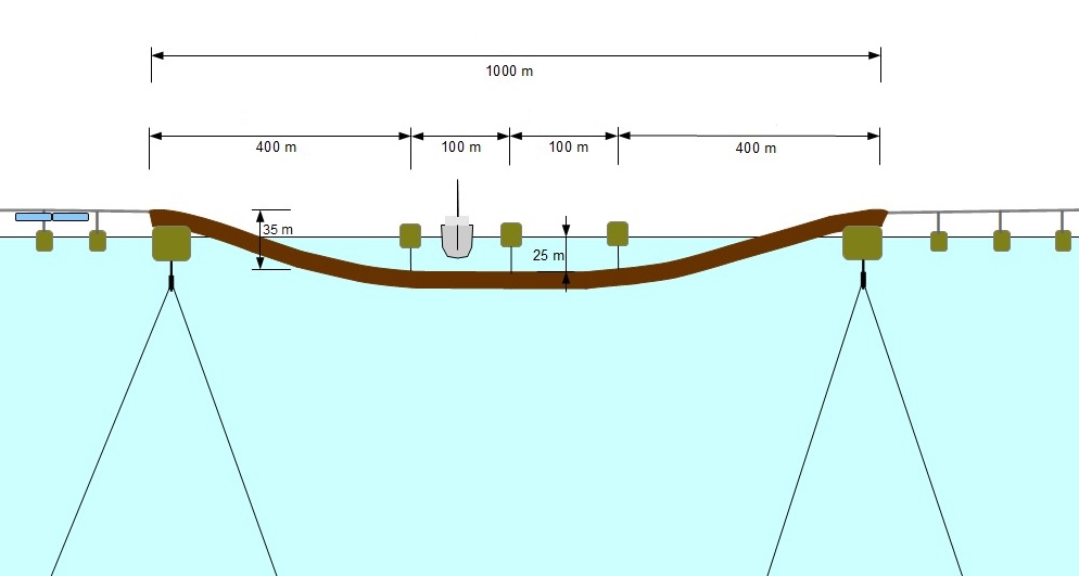
A submerged
floating tunnel like this is 1 km long, perhaps 4 meters thick, and
can be towed out from a shipbuilding yard. A pontoon-held beam can be
used for the rest of the crossing.
The submerged floating tunnel
has two full depth ship lanes. Small boats can cross almost anywhere.
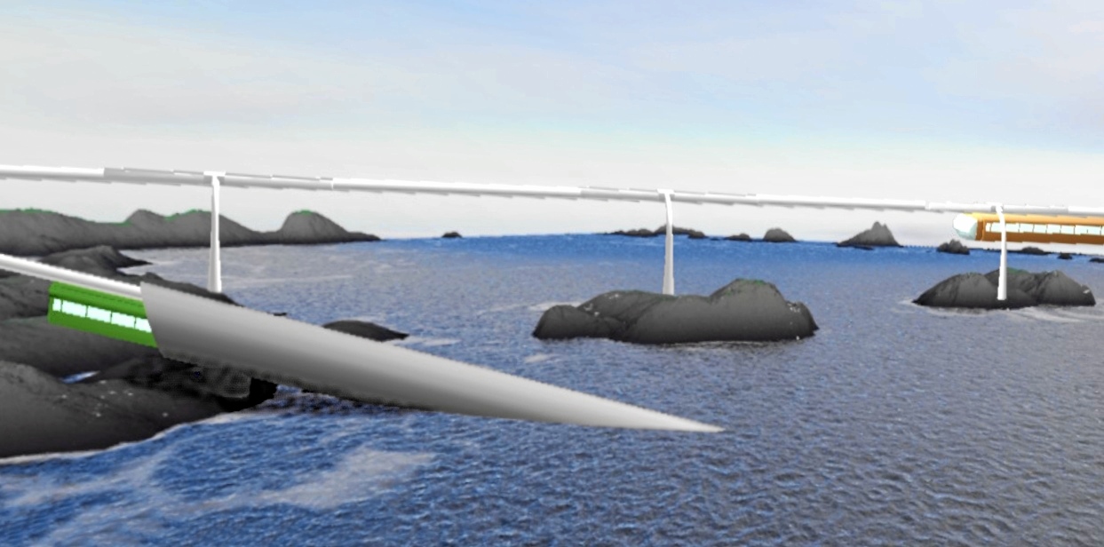
The beamway
can jump from rock to rock – also submerged ones.
The green
train is using a submerged floating tunnel.
If it isn't going
to cross ship traffic, it can go on a quite simple pontoon chain. If
it is to cross a wider channel or bay, it may use a submerged
floating tunnel, which (like the pontoon chain) becomes far simpler
and cheaper than a similar for cars or conventional railway. (See the
previous picture.)
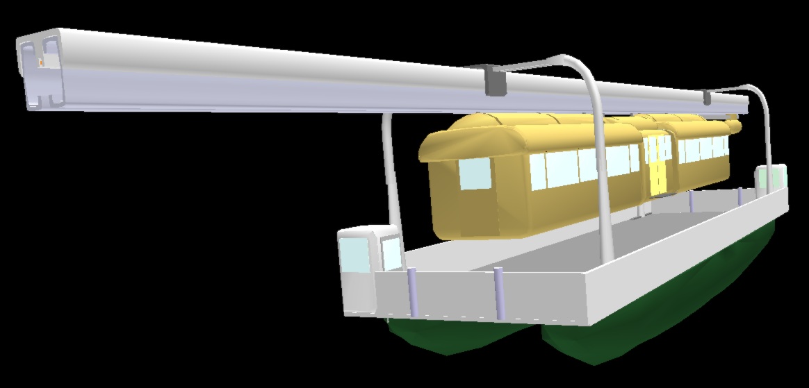
A
catamaran ferry for short trains. The receiving beam has a movable
end – for obtaining connection with the ferry's beam.
Also
electrical connection is obtained, so that the ferry can run on
rechargeable batteries.
The beamway
can easily do hill climbing by pinching the beam with powered wheels
– both from above and below
The hill climbing
capability means the submerged floating tunnel can use a quite steep
tube (best sheltered if going down in a bay).
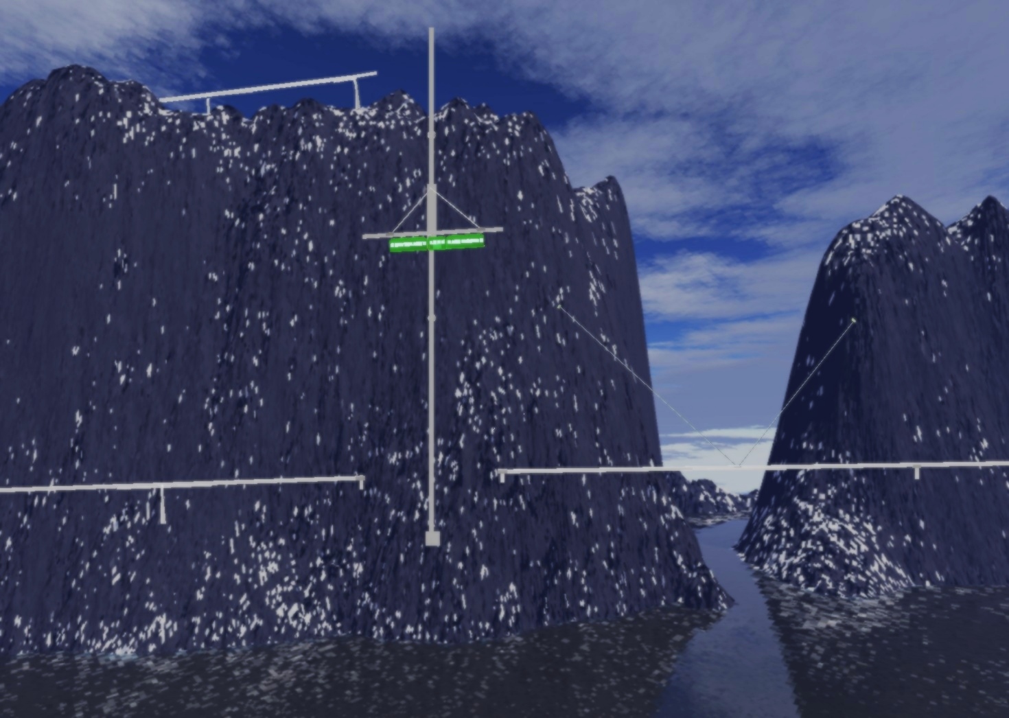
The
train takes the elevator up to the mountain plateau
Annoying
Penduling?
Will the
passengers be annoyed by train penduling due to crosswinds and
entering/exiting turns?
The proposed train
type can displace its suspension sideways. The wind may then simply
be permitted to displace the train sideways. The off-center
suspension will then by gravity counteract a tilt. This will not deal
with wind gusts, but the following mechanisms will.
The
wagon suspension can resist penduling up to the point where wheels
are almost lifted on one side, and this will give considerable
stabilization. (Centrifugal forces in turns will of course not be
counteracted in this way, as the turns have banking – tilted
beam – and an orderly train banking/sideswing will be
permitted.) Compressor-driven air cushion trains will be more able to
resist such swings, as the air cushions about to be lifted up can
adhere to the beam by suction, by reversing the pressure to an
underpressure. And a still firmer tracking can be obtained by having
air cushion units (normally
sucking) or wheels also at the bottom side of the beam.
At higher speeds,
the train can be stabilized wagons
by means of a set of stabilizers on the bottom – like anal fish
fins, but at least five side by side. The outer ones should be able
to detect side wind gusts, and the whole set should then be rotated
sideways to displace the bottom of the train towards the wind.
The beamway can
also increase the stability by using side support wheels. These can
be mounted on the lower edge of the wagons, and enable support from
side support rails installed on problematic line stretches (and
omitted elsewhere). The side support utilizes the ability of the
train suspension to shift the train to the side.
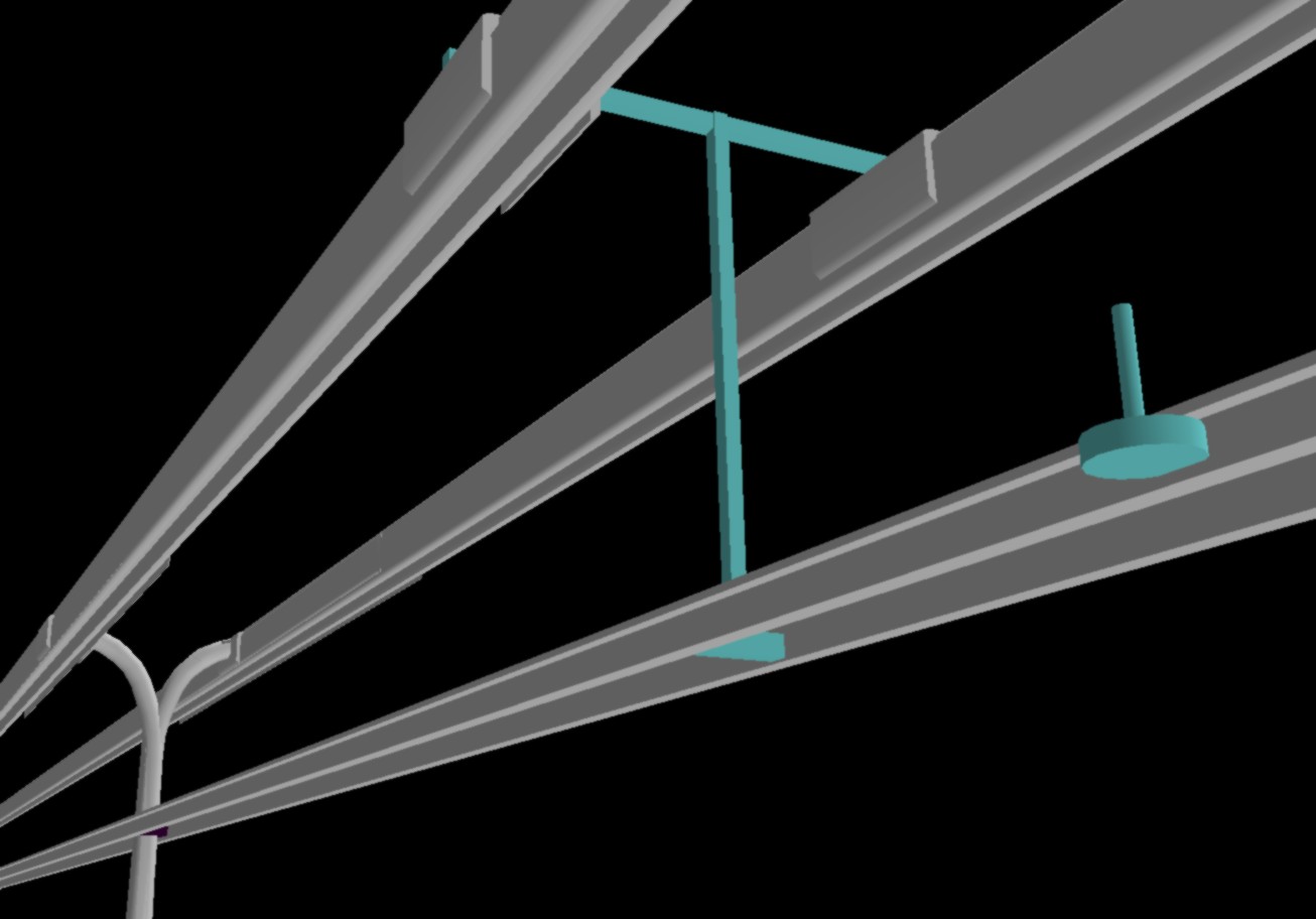
The train is
here shifted towards the support rail, which will then push
horizontally.
(Fine for air cushion units able to both blow and
suck this support rail, so that the train need not be shifted
sideways.)
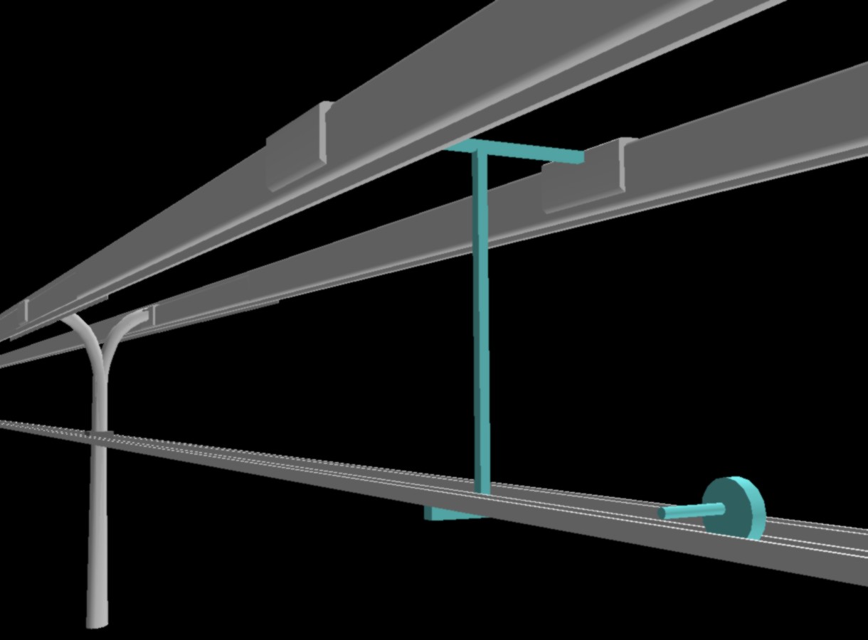
The train is
here shifted out from the support rail, which will then carry some of
the train's weight.
(Not so good when snow can fall on the support
rail.)
The T-shaped
support brackets connecting all the rails/beams will strengthen the
whole beamway and make greater pole separation possible.
Too strong winds
should not result in a sefety problem, as the train will merely yield
and swing to the side. This will merely result in passenger annoyance
– like during a turbulent flight. In strong side winds, the
beamway will be far safer than a bus. On windy stretches, the beamway
might get a tunnel.
The Safety
The conventional
railway is very sensitive to rail disturbances. It doesn't take much
of an avalanche or (mud/rock) slide to cause derailing. Even a quite
modest water flooding can wash away the ground support under the rail
track.
Under the beamway,
however, quite large avalanches/slides can pass without disturbing.
In risky parts of the line, the beam will be carried by racks having
one leg higher in the slope, and one leg lower. Both legs will be
streamlined in the cross-direction, and then it probably takes a real
rock slide to damage the track. (Wires going up a mountainside may be
used for extra safety.) If one rack collapses, the beam will bend
downwards and probably give a scary train passage near the ground.
(On such dangerous places, a staggered beamway configuration will
probably be used, with each C-shaped steel beam having its splice
near the middle of the other one.)
Driving heavy
trains is inherently a gamble – particularly through
wilderness. The train driver cannot know if the track is blocked or
damaged, and if such a situation is encountered, the train is unable
to stop in time. One then simply hopes that the train is able to
sweep away the obstacles. This assumption may be acceptable in flat
and simple terrain, but not with fast trains through wilderness.
By having an
embedded power line, the beamway avoids the problems and dangers
plaguing the conventional overhead wire system. A full beam
disruption will cause an easily detectable power line disruption.
Smaller beam disturbances should be detectable by checking
transmission of light, microwave or ultrasound signals through the
beam interior.
Collision with
other traffic or with animals are naturally rather unlikely. A quite
simple radar (and/or a tiny precursor vehicle) can easily detect
obstacles ahead the train, which then brakes automatically. And a
beamway train, which can emergency brake by pinching edges of the
beam steel, can have a very short brake distance.
In tunnels, there
will not be meters for traffic below, but half a meter may be
granted, so that people or animals straying in there may be passed,
perhaps toppled over, but not maimed.
In a tunnel or
submerged floating tunnel, a (quite derail-proof) beamway train is
unlikely to crash so thoroughly that another train is unable to pull
or push it out. The train's (hillclimbing) traction can also pull the
train out of a partially water-filled tunnel. Backup batteries in the
center wagon will be useful if the power rail is short-circuited. The
train's computer can easily be programmed for pulling the train out
of water – even if this involves filling the train partially
with water. Such an escape is feasible because the train will quite
certainly be alone down there – not in a chaos of helpless
vehicles. The terror threat will be far weaker when such emergency
procedures are known to exist.
If a suspended
train accidentally gets stuck, it can be necessary and problematic to
get the passengers down. A backup battery operated elevator in the
train will then be very useful. It is also useful to have
downhoistable passenger cabins. Both mechanisms should have extra
wire for emergency situations. If the ground is too far away, another
train can come to rescue and pull or push the stranded train, or
receive its passengers. Trains should therefore have doors in both
ends.
The safety can be
transferred to other traffic. Cars can be transported more safely
through a submerged floating tunnel by means of a beamway train. Road
tunnels can get an escape tunnel at practically no extra cost if the
beamway has tunnels alongside. (The heavy railway is less likely to
be nearby.) If the beamway goes in a road tunnel (behaving like a
bus), emergency preparedness can be improved by having remote
controlled beamway vehicles (with backup batteries) able to do fire
extinction, rescue/evacuation or pulling out vehicles.
Still further –
with Containers
As mentioned
above, the beamway can easily come close to other means of
transportation, but it would be best if the passengers could remain
seated in a cabin which could be transferred to another means of
transportation. On a section which already has conventional railway,
the beamway could – at least in a transition period –
cooperate with the railway. On a side track without overhead lines,
the beamway could go extra low, so that it could lower the passenger
cabin to a low well car. To hoist down passenger cabins hanging in
wires, will only be recommendable for small height differences, but
if the corners of the railway wagon has poles which can guide the
cabin, a few meters should be an acceptable vertical distance. Where
these operations take place, there will probably be cabin-handling
machinery to increase the safety and flexibility. They could for
example:
shift the cabin a
few meters sideways, so that the railway wagon can be, as usual,
under overhead lines
turn the cabin
90º, so that the beamway and railway lines can meet at a right
angle
adjust the cabin
position in cases of inaccurate driving
hold the cabin
for a while in cases of bad correspondence
With such a
transfer station a metro train can be supplemented with buses
meandering around in the suburbs. This is an application for special
cabins with side exit and spaces for back wheels (picture below). Its
truck has, like an ordinary bus, the entrance beside the driver.
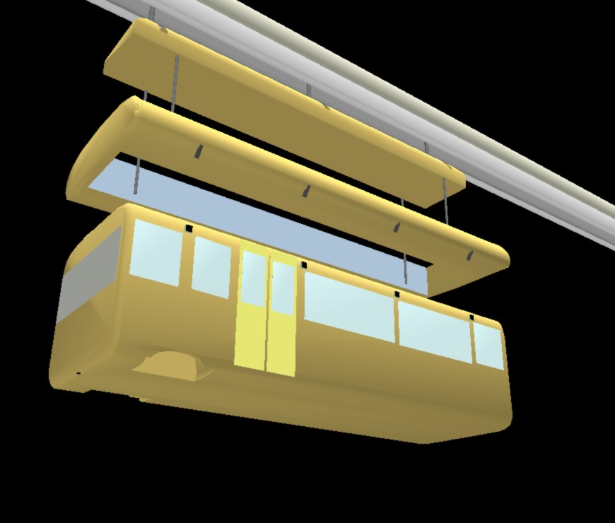
How to take
the bus.
Here we see how the beamway lowers down a frame having
teeth for grabbing by holes at the top of the sidewalls
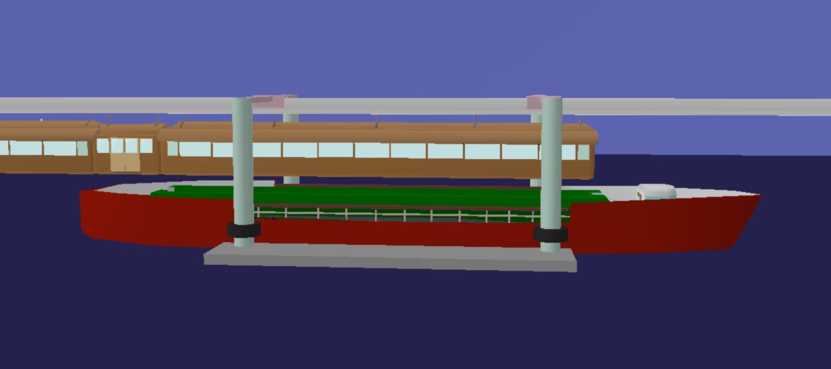
The beamway
could in special ferry harbors approach the deck of their ferries –
special barges having space for a cabin on the deck. This could also
be fast boats for quite long distances.
We here see a cabin ready
to be lowered.
(The boat can lower its wheel house, which would
else be in the train's way.)
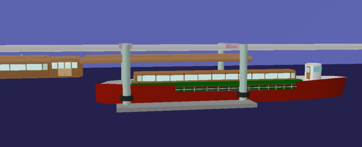
The cabin is
now placed on the boat, which raises its wheel house and leaves the
harbor
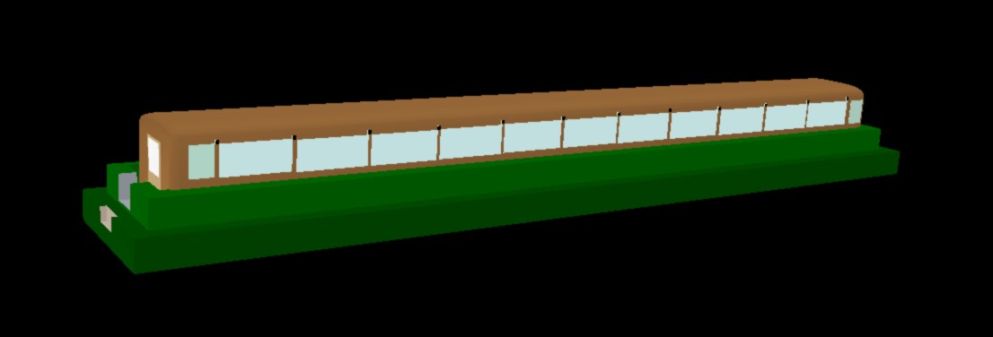
The bench
around the cabin is a large block of porous flotation material
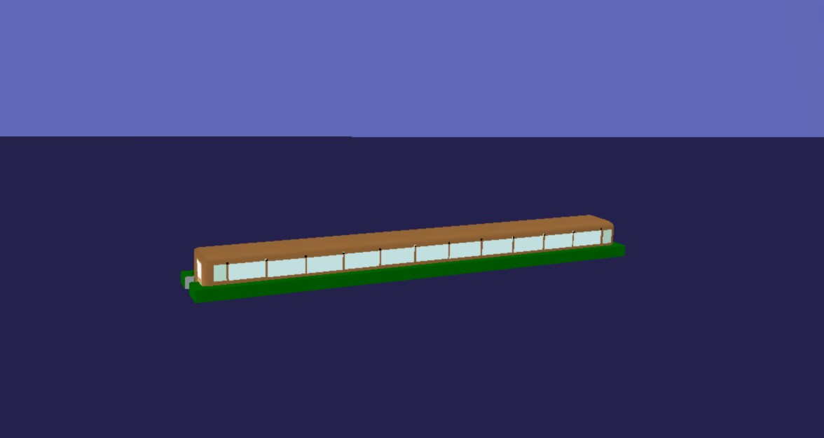
The cabin can
be kept afloat if the boat goes down.
Can any boat type be safer?
Such light-weight
cabins could also be sent into the fuselage of special passenger
cabin planes. Such planes would then have double walls, and thus be
far more bomb-proof. The passenger safety could be further increased
by giving each cabin a parachute in the roof.
As the airport
train cabins go into the plane, the airport can do without a
passenger terminal. Those wishing to dispense with the entire
airport, can send the cabins into a blimp.
Modular Cabin
Sizes
The module sizes
for the cabins should start with a maximal length corresponding to a
railway wagon – the brown one in the pictures. A suitable
length for this could be 24 meters, so that it could run like an
ordinary railway wagon if placed on a well car. The other lengths
should be fractions like 12, 8, 6 and 4 meters. The yellow “bus”
in the pictures is 8 meters long. The private cabins in the two last
pictures are also 8 meters long, but could have other lengths. A 6
meter car carrier could be useful for moving cars to and from places
lacking road connections – mainly islands within jumping
distance of the beamway.
A frame for
grabbing a 24-cabin could take a shorter passenger cabin (near the
center wagon) + one or more compatible mail containers. The frame for
grabbing the bus cabin could take two 4-meters mail
containers.
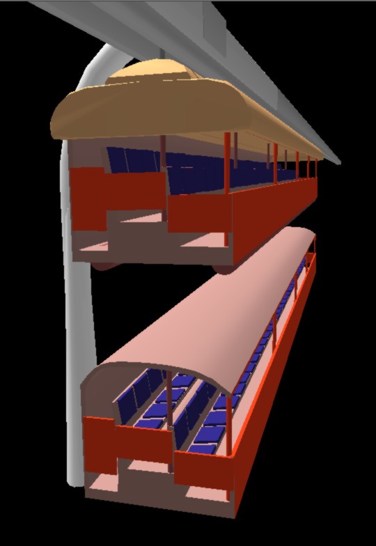
Grand
stand cabins – 24 meters long.
They could be placed
on the ground before use, or run with the spectators seated.
Also small
boats/houseboats could be produced in module format and with
compatible grabbable holes, e.g. in the rail as shown in the picture
below. Everything else can then be shaped as a real boat, so the
difficult combination design of amphibian crafts is avoided. Wherever
a beamway takes a shortcut over water, such a boat can be lowered or
hoisted. It may become practical for inland people to do this for
every boat trip. And large boat-houses for beamway-launchable boats
may become popular.
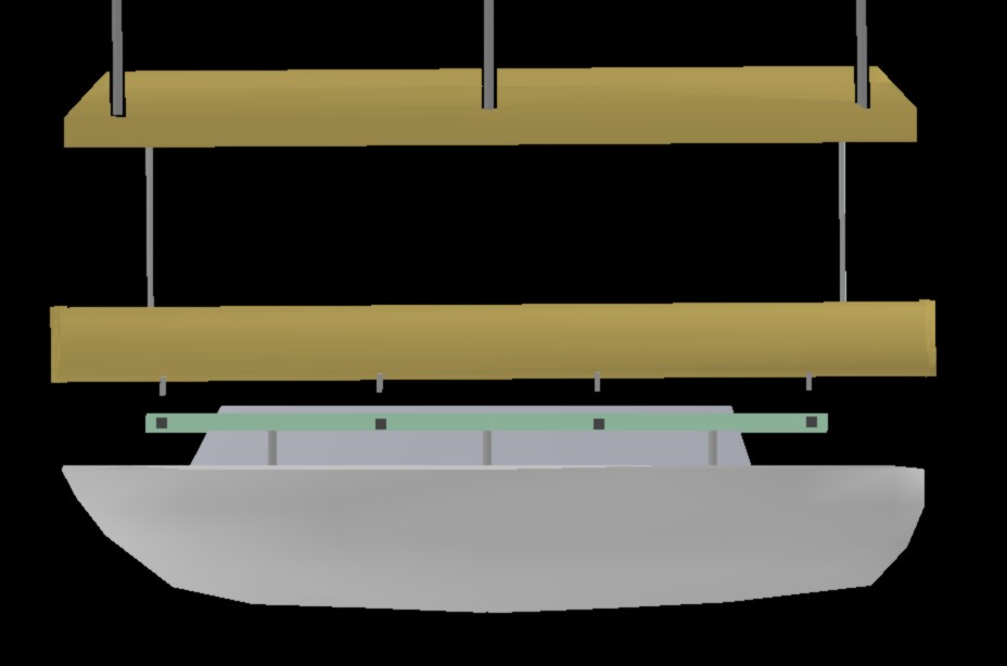
A boat with a
rail which can be grabbed by a standard frame.
Ordinary boats
could be transported short distances held by loops under the hull.
Cargo
As long as the
weight load on each beam length (30-40 m) doesn't exceed the load of
passenger transport – 2-300 kg for each meter train length –
the beamway can of course be used for cargo transport. This load can
be reduced by using cargo wagons with a smaller cross-section area,
and have several meters between wagons. The cargo train may then
become quite long, but due to the higher acceleration of this light
train, it can avoid getting in the way of other trains. The reduced
transport efficiency caused by having intermixed trains with strongly
varying weight and speed is avoided.
The limited cargo
weight is largely compensated by the adaptability of this rail
system. This is also related to the possibilities for automatic
(unmanned) driving above the ground scene, and the fact that the
track can go over factory fences and into manufacturing halls.
The beamway can
take care of the fuel transport of the future by transporting
hydrogen tanks. These need not be compact, having high pressures. A
few hundred atms will be fine.
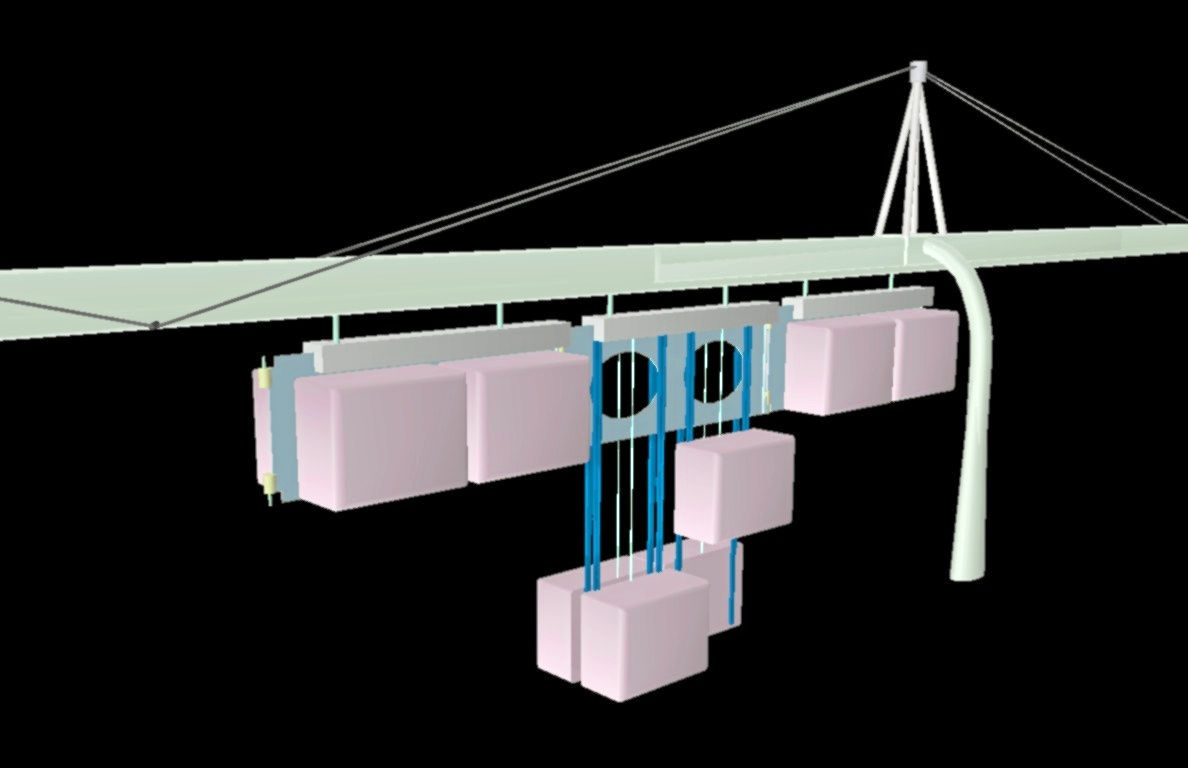
Cargo
containers hang on the sides of this special freight train, and can
be put down on a shopowner's pickup – no station needed.
One
or more containers can be replaced by a motor pack – no
locomotive needed.
These wagons with vertical chassis are optimal
for controlling and distributing the load along the beam.
This
beamway is reinforced with (carbon fiber) wires.
Additional Passenger Wagons
A passenger train may be extended with
additional passenger wagons at the front
and/or rear. The passengers in these must go through the regular
wagons, so normally additional trains would be
used instead. Extra carriages may, however, be
appropriate if they provide extra facilities
for existing passengers, and not used for increasing
the number of passengers - at least not with a normal passenger
density.
Such
supplementary wagons can provide:
These
are not needed for short trips, so the
walk through the regular
passenger wagon will not be too annoying. As
the passenger densities
in these extra wagons are
small, the train will not become too heavy. This is because the extra
wagons to a small extent increase the weight load on the same beam,
but rather on the neighboring beam and the
pole between them.
Private Pods
It
is popular to propose new transport systems based upon privatized
small wagons – often called pods – and often as
automatized taxis running on rails or under beams. These proposals
imply establishing a new transport infrastructure directed at the
transport needs of quite small regions, and they tend to disregard
the handicapped, groups needing more than one pod, as well as the
need for using toilets during the trip.
The
variant to be proposed here follows our principle with a passenger
cabin being detachable from the bogie under which it hangs. (A bogie
is a little motorized 4-wheeled "wagon" running inside the
beam.) These small cabins are so simple and versatile that they are
likely to often be privately owned. They can, as depicted below, be
carried inside carrier wagons in high-speed trains for long trips, or
upon rented or owned cars/boats.
When
the cabins are held in the carrier wagon of a fast train, the
passengers can walk through a corridor to and from their cabins, the
cabins of companion travelers, the toilet and perhaps a (food) store.
They needn't complete the trip as a pod traveler or a train
passenger, but can change status on the train, using the train's
elevator only at the start or the end of the trip. Or they can join
the group in another wagon.
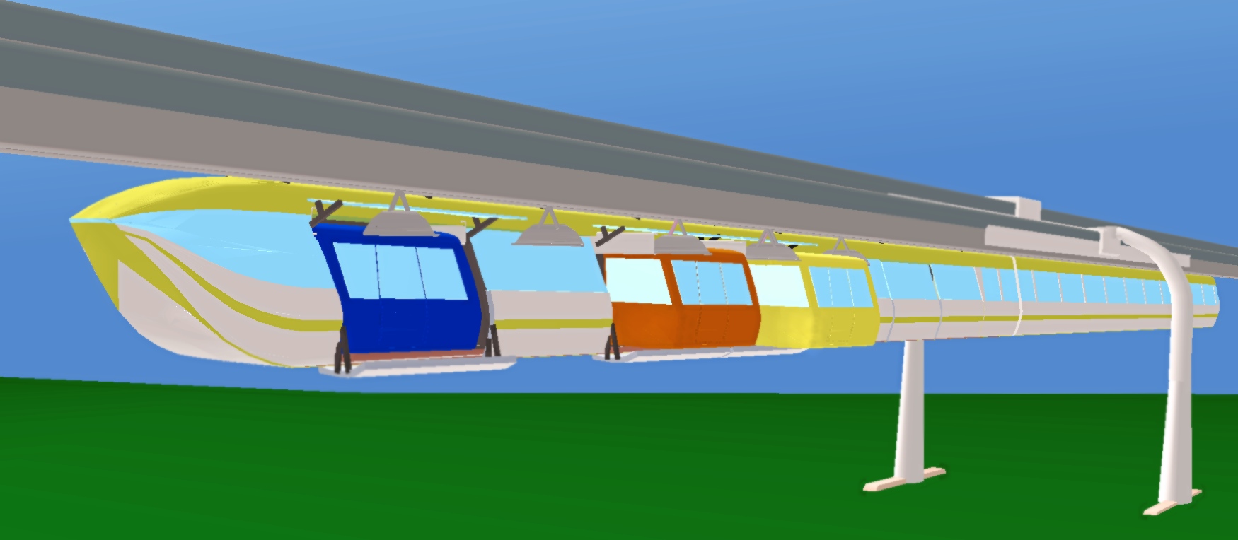
Small
cabins (under the nearest beam) are here transferred to and from the
rear wagon of a train (hanging under the mostly concealed beam). This
pod carrier wagon can carry 8 pod wagons. The blue wagon has moved
sideways all the way into the carrier, the brown one half-ways in,
while the yellow one is still in normal position under the beam. The
(upper and lower) doors are still closed for the 5 remaining
compartments.
The
cabins have small, motorized wheels fore and aft on the top, so that
they can move sideways along the transverse mini-beams they are
suspended under. From these mini-beams (hanging under the front and
back of a bogie), a cabin can move onto abutting mini-beams hanging
under the ceiling of a carrier wagon or a parking facility. Cabins
can be stacked in multistory parking facilities, as they (and frames
with the mini-beams) can be hoisted and lowered by wire (up to 6
meters). This movement can be used for emergency escape in normal
terrain.
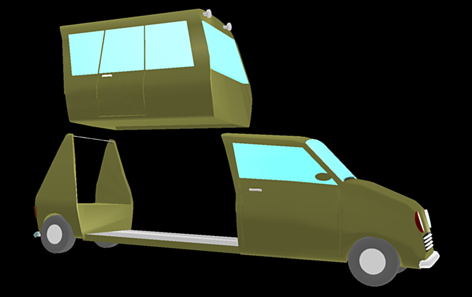
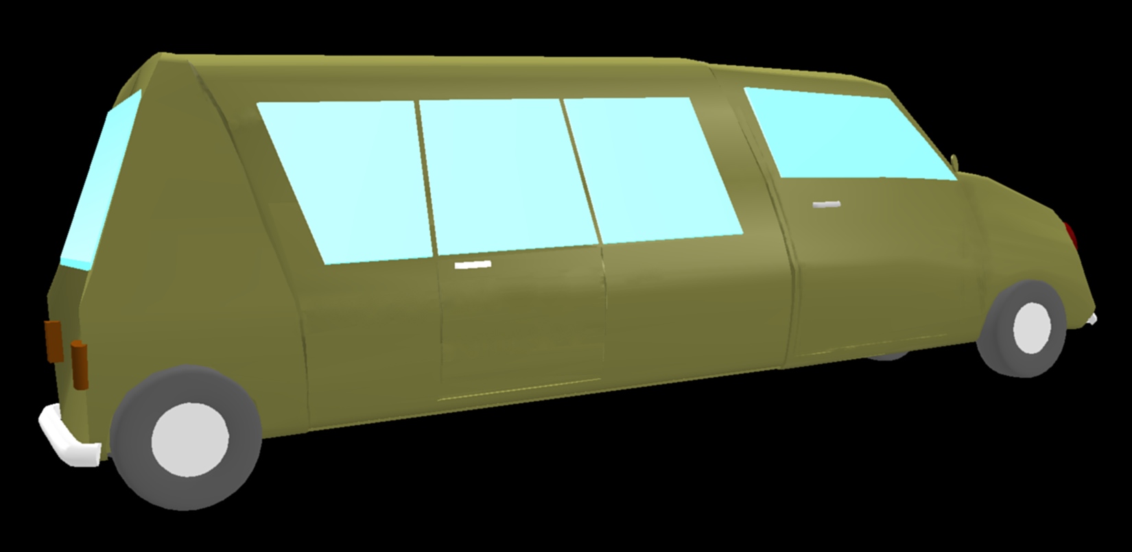
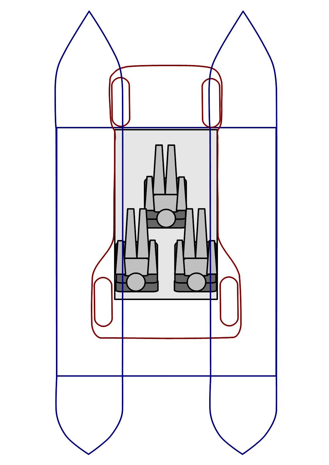
This
shows how a 2.5x1.5 meter cabin can be positioned upon a small car
(red outline) or a catamaran boat (blue outline).
Without an
external driver compartment (which the limo-sized vehicle above has)
the most space-saving seat arrangement, with two reversed seats along
the front wall, may not be used.
This car (like the previous
limo-sized one) gets a rear baggage trunk when the top-hinged back
door is swung somewhat back.
It
may be concluded that either of two seat configurations are likely to
be chosen for a cabin, depending on if an internal driver's seat is
needed.
Cabins
with not more then a few folding seats may be used by wheelchairs.
For privately owned cabins, many layouts may be used, with foldaway
berths, baby seats, storage furniture, etc.
Cabins
can also have wheels, motor and batteries, so that they become
complete cars. But these will become two-seaters with small wheels
and inferior driving characteristics – mainly for local
driving.
Transport of Cars
Beamway trains for
cars may be useful for various purposes. They can carry cars to
places where a road connection will be too expensive and/or bad for
the environment – e.g. to sparsely populated islands. Or they
can carry cars through a submerged tunnel, where centralized
operation is important, and where combustion engines cannot be used.
But even if there is a good road connection, a car-carrying beamway
will be a good idea – because:
The train can go
2-3 times faster than cars, and with far greater safety.
The driver can
spend the time doing something useful – like resting.
Toilets will be
available during the trip.
CO2
emissions are greatly reduced.
Electric cars get
a very different operating range – especially if they can be
recharged during the trip. The car batteries may then be used by the
train as backup batteries.
A wagon for cars
will have approximately the same shape and appearance as a passenger
wagon, but can be made extra long and rigid, so as to not weight down
the weak central part of the beam. The wagon's ends – made
round and aerodynamic by containing toilets – can slide/swing
aside, permitting cars to pass through. The cars are not obstructed
by the next wagon, as the gap between wagons can be several meters
wide, and a wagon can be rotated sideways by displacing the ends
perhaps a meter to different sides.
At the stations,
the beam should be so low that the wagons are just above the ground,
and then one or both wagon ends can be lowered to the ground. This
can be done by means of wires which are so long that wagons in an
emergency can be lowered from normal beam height. The station may be
a ferry deck, a bridge or a building.
Trains carrying
cars will not be particularly heavy. A load weight of 300-350
kg/meter should be about the same as an ordinary passenger wagon
should be designed for. Actually, a passenger wagon must be designed
for far greater local loads, as its contents may lump together in one
end of the wagon.
Mobile
Services
The automatic
driving enables services which have previously been impossible, or at
least uneconomical. A traditional bookmobile, for instance, is about
12 meters long and needs both a librarian and a bus driver. It can be
replaced by a beamway wagon which might be 24 meters long and can do
without a driver. A simple little sidetrack beam is needed for each
stop to be used by this "book tram" and similar services.
As passengers are not transported, the cabin can simply be lowered to
the ground by wires. It can still have power connection there.
At the day's end,
the wagon is hoisted up, and is then quite well secured. It might
also run to a similar sidetrack near the librarian's home.
The same principle
can be used for e.g. various medical services: mobile dentist,
polyclinic, blood bank...
The strongly
reduced expenses for wages and fuel could lead to a closedown threat
being turned into expansion plans.
Such a service
might become rather one-dimensional, but if it had been more
two-dimensional, a structure coarseness could still necessitate
supplementary short distance transport like car, bike, taxi, local
bus... It might actually be easier to obtain an efficient local
transport system if short trips to a beamway stop are known to be
needed frequently.
If the mobile
services are needed at many locations, downhoistable cabins (like the
yellow bus cabin depicted above) for use on special trucks may be
used. Then a local driver can be engaged for just two small
assignments: Move the cabin from the beamway to the point of service
in the morning, and then move it back again in the afternoon. Very
long cabins (perhaps 24 meters) can be used on roads when it is known
on which stretches they are to be employed. Long cabins are easier to
handle on the road if they and their trailers are articulated like an
articulated bus.
Kindergartens can
have their own trains running around in residential areas picking up
the kids in the morning, and going out to deliver them in the
afternoon. If parents are too late with their delivery in the
morning, they deliver to a local short-term kindergarten instead. And
if parents are not showing up in the afternoon, they do the pick-up
at that place – which may be a wagon able to move as called
upon. Anyway, parents should be able to manage without cars.
The main
kindergarten can be a large, central facility quite far away, and the
wagon can be the child group's own room here. It will also be simple
to go driverless on excursion to various places.
Also schools can
obtain such an economy of scale when students easily can be
transported quite long distances, but these students can use the
normal trains. Alternatively to obtaining economy of scale, the
school system can make special educational varieties available for a
large area.
Running
(between) Hospitals
Hospitals will be
the first candidates for using a public beamway network for their
"private" purposes. That is: They should be able to
dispatch their own (mostly small) wagons to and from their own
beamway stations in hospitals. Transport of patients, medical staff
and parcels (with medicines, equipment...) between hospitals can be
automated like the pneumatic tube systems used in hospitals.
Ambulance vehicles – and even wagons from normal trains that
happens to become involved – can run directly into the
emergency room.
This will be
possible because long distance lines (for e.g. 200 km/h) and local
lines will use compatible and interconnected beamways, with computer
controlled operation. This automatization is easy because the beamway
vehicles are alone in their elevated level. The local lines will of
cause get a stop within a short walk from each hospital. The only
line connection costs falling upon a hospital will then be for
building a beamway beam (normally 100-200 meters long) going into a
hospital building.
Being able to run
between hospitals in this manner will enable running hospitals more
efficiently and economically.
Post
The beamway is
able to dispatch more or less private wagons automatically, and this
ability could be used for at least delivering parcels. The central
element will then be an automat for storing and delivering parcels of
various sizes – like a vending machine. The wagon – a
robotic postman – will need such a mechanism for organizing the
parcels it distributes. The mechanism needn't be burglar proof, as
transferring parcels to the delivery automat is automatic. Each
parcel might be stored in a cloth bag, as these easily can hang or
lie together in a space saving manner. When the post wagon arrives at
the delivery place, it transfers the parcel to another automat. This
is – like a vending machine – accessible to the general
public, so it must be rather burglarproof. It might have a shelf,
perhaps rotating, with movable dividing walls ensuring efficient
space utilization. The recipient opens the correct partition with a
key or access code. Two shelf sizes may be needed, having different
cross-section areas, for accomodating a wide range of parcel formats
economically. But some parcels will be too large for a neighborhood
facility, so the recipient must take the train to a post office –
which might have a staff.
Alternatively,
parcels can simply be placed in the open on the delivery site. The
recipient will then acknowledge an arrival message by phone, and
later signal he is ready to pick up the parcel on the site.
To send a parcel
is somewhat more complicated. The automats could be made reversible,
but the system must have the destination address machine-readable. It
could be entered with an app on a cellular phone (which can check the
address in an address database), or a USB stick with the address in a
certain file could be plugged into the automat.
If this system
becomes cheap and simple, it might also become used for goods to be
recycled.
A new Tourism- or
Home Type
When passenger
transport in standard cabins starts becoming common, people will buy
their own camping cabins and perhaps compatible small boats. Special
cruise ships for these will actually be container ships which have
platforms for private module cabins instead of normal fixed ship
cabins. When the passengers arrive at an interesting destination, a
beamway beam will be pushed in over the ship and lift up the cabins
of the passengers who want to get ashore there. They will then be
transported to the campsite (or small boat harbor) of their choice.
For the passengers, this will be much simpler and cheaper than
traveling with a private motor home.
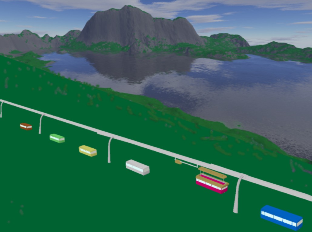
Another
camping cabin is put down on the camping site.
With a simple servo
power mechanism, the user can pull the cabin a few hundred meters
away from the track.
If a recreational
beamway goes from a coastal town and up to the mountain, it could
carry people's cottage cabins for perhaps short winter stays. It
could then pass near skiing hills and function as a ski tow. If it at
the coast goes out in the water, small wagons could pull water skiers
– and the beamway could carry small boats to the sea or up to
storage.
It is now common
that people get a cabin or summer place in the mountain and/or at the
sea, and they may have a boat at the seaside. This may be used for
only some weeks each year. Or they may have a motorhome/RV, 6-12
meters long, and might bring along some bikes and an inflatable boat.
It is a demanding and slow task to move this around.
With beamway
cabins, however, people without a driver's license can easily,
rapidly and quite cheaply go on vacation in their own vacation cabins
or home cabin – perhaps 24 meters long. Such a cabin could have
a separate water section that could be moved (servo pulled) to the
place where drinking water is filled and waste water/compost is
emptied.
Vacationers may in
their neighborhood have a secure cabin storage place where they move
into a preheated cabin, and then let this be transported to the
vacation resort of choice in perhaps 200 km/h. And they may
additionally get a beamway-compatible car, minicar or boat. Even if
crowds should choose to do this on public holidays, the beamway can
handle such a stream of cabins with high speed and safety.
If
a moderate cabin length (6-8 meters) is used, the cabin may be placed
upon a bus chassis, and may then be driven around like an ordinary
mobile home – as shown in this
chapter. This chapter also shows how cabins (up to 24 meters
long) can be used as/with a houseboat.
As such cabins can
have an area of 50-60 m², they can
have extensive use as homes. If a home needs more than one cabin,
these can be moved while tied together by means of a somewhat
flexible connection. Or the cabin can have extendable/retractable
side walls. A cabin home can have a garage with a car in one end.
This mobility can
be useful for going on vacation in the home. Or when changing
workplace (or life companion).
When homes are
relocated like this by the beamway, the governmental address files
may be updated automatically. Delivery of parcels,
groceries etc., as well as removal of garbage can easily be
automatized.
A
really two-dimensional residential area can be covered by means of
beams that can be moved
sideways.
The terrain
needn't be so flat, because when a cabin has been lowered to the
desired height, support legs can be lowered to the ground. Cabins on
legs will also be more flood resistant. If a flood destroys the
terrain, cabins can simply be lifted up and perhaps moved away.
Private cabins and
public train cabins can share a common system for cabin movement (by
beam or boat), data communication, power supply, water supply, toilet
emptying, garbage disposal, external cabin washing, cabin repair
etc..
When cabins are
placed from above, they can be placed upon sockets which give
connection to electric power, water and sewage.
Commuters
When the economy
of passenger transport forms are evaluated, the crucial point is how
far people will want to commute daily with the transport in question.
About 40 minutes each way is commonly accepted. But an important
point is: Will it be possible to work with e.g. a laptop computer en
route? In this respect, the train is commonly regarded as superior in
comparison with the bus. Trains may have office compartments, and
this seems to be unfeasible in buses. This may be due to the limited
passenger area available behind a bus driver.
The beamway will
in this respect have the train's advantages, as it can have much
passenger space without requiring more (driver) manpower. Office
wagons may be attached at the front or rear of an ordinary beamway
train, as they are used by few passengers taking not so short trips.
Or special commuter trains may be used – for special
subscribers managing without staff help. Wagons with office space may
be useful for airport trains, but it is much more difficult to extend
a conventional train track out to an airport.
Commuters often go
to and from cities. At city stations, conventional trains usually
have to move slowly through complex track systems, whereas a beamway
train quite rapidly can get up to full speed – perhaps 200
km/h. The acceptable commuting distance should thus exceed 100 km.
The miserable
weight adaptation of conventional rail will be really blatant when
the extra lightly loaded office wagons are used.
The Disabled
This is about a
suspended monorail with an elevator, so that passengers walk –
or drive a wheelchair – onto a floor about 5-10 cm above the
ground level. The floor could be a few centimeters thinner at the
door, and a threshold ramp can be pushed out there, so that
wheelchairs can easily roll in and out. And this applies to stops on
any level ground, so that special platforms will not be needed. At
some locations, or at some times, the traffic schedules could be so
flexible that stops (with elevator use) could be improvised at rather
random places. (Sending home people at night, or children/disabled.)
The competing
ground traffic vehicle types are car, bus, tram, light rail and
train. They all have the floor above a chassis causing a height
difference of at least 20 cm. This is much. A train as much as 5
meters above the ground will reduce the height difference to 0 cm
thanks to its elevator.
Wheelchairs will
need special platforms for accessing the top of a chassis, and this
implies designated stations, adapted to certain wagon shapes. It is
certainly possible to make special wagons where parts of the floor
can be lowered towards the ground through the chassis, but such
facilities are likely to remain quite rare.
Also motorized
wheelchairs will be able to drive into the elevator. But some of
these are quite large and heavy, so their prospects for being
admitted will depend on circumstances, necessitating a call to the
transport company when such a trip is planned.
Beamway wagons
could near the elevator have a seat-free area, perhaps two meters
long – for bikes, wheelchairs and large items. Such a weight
spreading suits the beamway well. Compact transport is not of
interest here, but rather long wagons in short and cheap trains.
Long trips will
normally entail a combination of short-distance transportation (like
bus) and long-distance transportation (like train). The beamway is
quite unique, being suitable for both local and long-distance lines.
When these two are combined, they can and should be properly
integrated, so that the local lines not merely give connection with
distant long-distance lines, but are really useful as local lines.
When the two meet, wagons or cabins may be transferred. But even
under technically simple conditions, the transfer is simple for the
passengers: Go (or roll a wheelchair) between the elevators of the
two trains – something like 3-50 meters.
By having a
conductor at the entrance in the elevator, the beamway train can give
special service also for the disabled.
The
Environment
If uneven terrain
has to be levelled as required by conventional railway, there will be
much dynamiting and landfilling in some meters' width throughout the
landscape. And the railway line constitutes a barrier almost all the
way (and/or it often kills many animals in its way). The beamway,
however, takes just a fraction of a square meter for a single or
double pole, and this with 30-40 meter intervals. Several meters of
terrain height variations are compensated for through pole length
variations. This amounts to a 99% reduction of both terrain razing
and barrier formation. If the beam is carried by movable racks
standing upon the ground, there may not be noticable traces remaining
if the whole line is later removed or moved.
Also
the urban environment is improved if the light rail is really light,
able to go "upstairs". No house must be removed, no road or
street closed. Elevated traffic can use much higher speeds than on
the crowded ground level. The car drivers will then discover they
could reach their destination quicker by rail, so "Park
and ride" could finally become popular.
No
matter how fast the elevated traffic runs, children will be safe down
on the ground, as they simply can't get at the elevated vehicles. If
the elevated traffic should become too annoying, it is easy to put it
under the
ground.
If a road or
railway line is already going in the right direction, it is easy to
place a beamway line above it. Terrain levelling that has been done,
will simplify the beamway construction. New rail bridges will not be
needed, as the beamway goes along on old bridges.
Light-weight
trains will naturally use less energy for overcoming gravity and
friction, but the air resistance will be the same, as it is
independent of the weight. The beamway's beam will, if it goes
approximately in the east-west direction, be a fine carrier for solar
cell panels. The beamway system has already the area, technical
personell, cabling and now and then a local power consumer.
Standard railways
use freely hanging overhead power lines emitting much electromagnetic
pollution. The power line of the beamway, however, goes in the
interior of a steel beam which blocks the electromagnetic fields
quite efficiently.
Lots of people try
to be environmentally conscious, but have an antitechnological
attitude they believe is conducive to protecting the environment.
These people tend to end up as supporters for the old heavy rail.
This is a dumb attitude which does real environmental protection a
serious disservice.
If the Beamway Fails to
Perform
The greatest point
of uncertainty is: Will a beam with the suggested dimensions (80 x 80
cm) be able to carry the weight of cabins big enough for bus/train
use? If this turns out to be problematic, the distance between the
poles may have to be reduced from the suggested 40 meters to perhaps
less than 30. The savings in ground consumption/razing will then be
reduced from 99 % to perhaps only 98 %.
But what if such
problems are encountered after the beamway is built? The beam is
symmetrical, so it can simply be turned upside-down if it sags. It is
also feasible to simply bend the beam by pressing its middle part
upwards. This is quite easy because the beam is split along its
length, so that one half can be bent at a time.
Besides, the beam
could be reinforced with wires going up to towers (extended poles),
or the load on each meter of the beam must be reduced. We could start
by assuming the passengers will be sitting 2+2 abreast like in a
normal 2.5 meter wide bus, and with normal legroom. If the beam turns
out to have less carrying ability, one may have to go down to 2+1
abreast, as well as far more legroom. And consequently the train
departures may become twice as frequent.
The passengers may
very well hope to get luxury transportation this way.
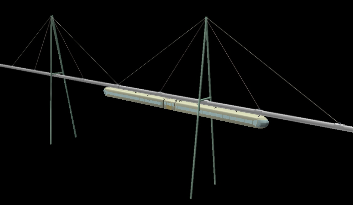
With
this beam suspension method, it is (in cases of problematic beam
sagging) easy to get a short distance between the suspension points,
or to move them to the sagging beam parts.
The number of poles is
also reduced, giving less disturbance of e.g. agricultural
areas.
(The towers can have single pillars if needed.)
Large
towers can be some hundred meters, perhaps a few kilometers
apart.
Quite uneven terrain can be traversed in this manner.
Existing
Beamways in Germany
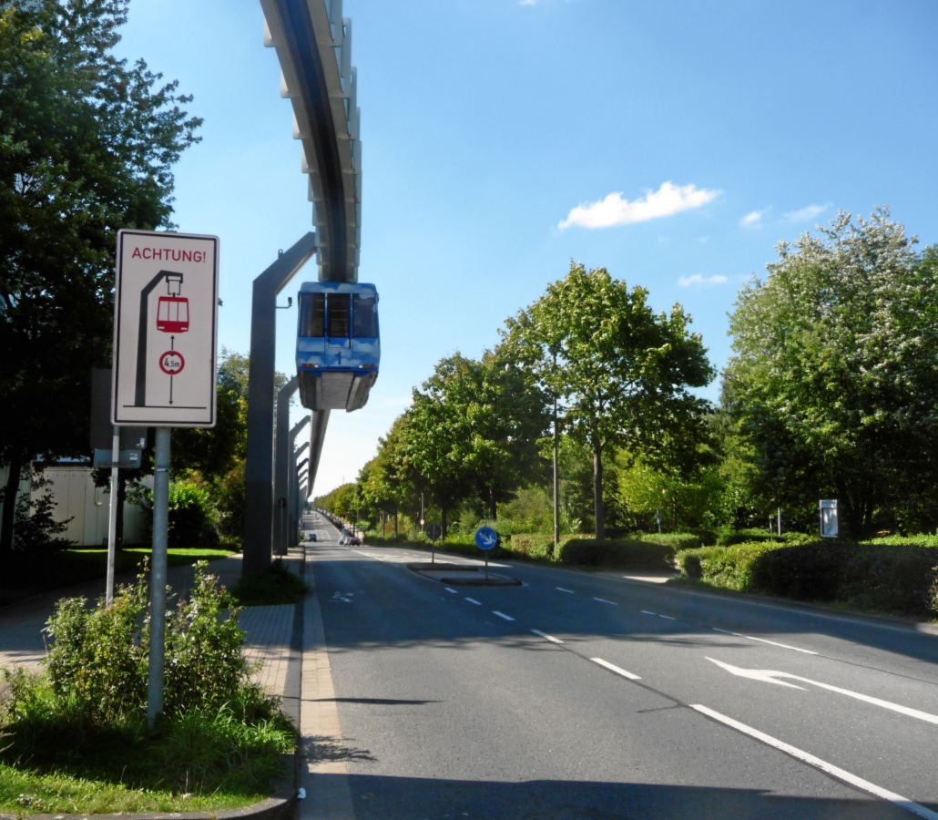
Single-track
beamway (the H-bahn) in Dortmund
The sign indicates the maximum
height for vehicles on the road: 4.5 meters.
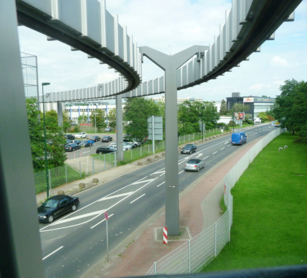
A
double-tracked beamway in Düsseldorf
(the SkyTrain at the
airport)
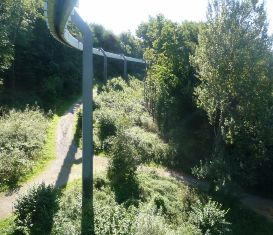
We
fly through a forest in Dortmund.
The common
line construction procedure is to raze and level the ground, so that
a barrier is obtained – upon which trains will struggle with
snow in the winter. The trains should be heavy and complicated,
requiring skilled drivers.
The trains here are unmanned.
Both
these SIPEM lines are computer controlled.
The
rib structure on the outside of the beam serves to stiffen the sides,
so that they will not be bent out by the weight load on the inside.
According to the present proposal, full width wheel axles are
avoided, and then a varying track width will be ok.
The Main
Points
The
beamway (a suspended monorail) can:
avoid
being a barrier for animals and people
follow
the roads – also over bridges – and take some shortcuts
have
its tunnels alongside road tunnels, which have then obtained free
escape tunnels
follow
the old roads near towns, and still run at high speeds
be
carried by mobile racks, so that lines can easily be rerouted
along
the coast jump from rock to rock, have pillars in the sea, go on
pontoons, or go through submerged floating tunnels – also for
transporting cars
negotiate
steep slopes (more than 10 %), and be uninfluenced by snow and icing
stop
almost anywhere and have an elevator (wheel-chair friendly) for
entering/leaving passengers
be
used for both urban and rural lines – also in very difficult
terrain
send
patients, medical staff and parcels (with medicines, equipment...)
between hospitals as if by the pneumatic tube systems used in
hospitals
strongly
reduce the need for train drivers – as the upper level traffic
can easily be computer controlled
(Minitrains can go unmanned,
like an elevator can)
be
economical at low traffic loads
give
increased safety
save
much energy and CO2
This
was a listing of the advantages, and a corresponding listing of the
problematic points may be expected. But the list is written by a
problem solver, and this website contains material tantamount to a
book about how the various problems can be solved. This is mainly in
The
Beamway – Technical details.
The
main concern is adressed above in If
the Beamway Fails to Perform.
Copyleft
 Olav
Næss 2006-13.


